
5-Stage CW
I have recently had the desire for HVDC, so began the Cockroft-Walton voltage multiplier project. Actually, to be more correct it is a "voltage adder", as each stage adds the peak input voltage. The goal for this project is for a 150kv output. A 5-stage multiplier actually produces 10X the peak input voltage, so that means I need 15KVAC into the CW for 150KV out. This does not take losses and loading into account, so to make up for that, my aim is for a 20kv peak input. This 20kv comes from a hand-wound transformer (by yours truly) that operates at 50khz+ (actual operating frequency is yet to be determined). This project has presented me with some interesting challenges (which is one of the reasons I chose to build one). Firstly, I had to design a HV transformer to run at ~50khz and 1500W continuous output. This is not such an easy task. Insulation is very hard to get right at this frequency, the AC will just arc through most things without trouble. The other major challenge is building the CW stack itself so that it doesn't suffer from too much leakage as well as having a very large stand off voltage.
TRANSFORMER CONSTRUCTION:
Here is the transformer that I designed for this project. I in fact burnt up many secondary windings to get where I am now. 2 important things: 1) corona suppression is a must, 2) don't put too many turns per layer of winding. Anyway, there are 500 turns on the secondary coil. This may sound like a very small amount until you realize that the ferrite core is good for some 35V/turn! I am using resonance to my advantage, and running it "quasi-resonant" at a frequency somewhat lower than resonance as this was found to produce the best results when driving the CW. The primary is some 20 turns of 16awg magnet wire, though this is subject to change as I experiment. I used 18 mills of PE film between each of the 12 layers of winding on the secondary. The layers are somewhat tapered. The first layer has some 80 turns of 26awg magnet wire, while the 12th layer has only 20 turns. Its best to go with fewer turns per layer as this will reduce the inter-winding capacitance. After the coil was wound, I vacuum potted it in paraffin wax, inside of some 2.5" PVC tube. This suppresses corona, which is the ultimate failure mode for HV transformers. Corona will eventually eat away the insulation and cause internal arcing. I still have some fear that this may eventually happen, if so it will give me another chance to make the next transformer even better. Below are a few pictures of the secondary before potting it in wax. The final product is shown to be working producing sparks that start at about .75", indicating that I am near my 20kv (peak) goal. The transformer shows no sign of heating at this power level.
![]()
TRANSFORMER DRIVER:
The transformer driver was quite easy with my past experience behind me. I opted for a full bridge of IGBTs to switch 170VDC into the primary coil at some 50-100khz. I used a TL494 to produce a square wave, which is then buffered by a pair of gate drivers. The drivers drive a gate driver transformer, which of course, drives the gates of the 4 IGBTs. This whole driver should be good for 2kW continuous power if I need it. Here are a few pictures of the driver:
HV DIODE CONSTRUCTION:
The HV diodes are actually constructed from strings of small diodes wired in series. The particular diode I used (purchased from Newark) is the SF1600. It is a 1600V, 1A, 75nS Trr, avalanche rated diode. I went for 1600V as that was the highest available for the "cheap" diodes. The 75nS Trr is important for running at these high frequencies, so that recovery losses are not significant. The avalanche rating is especially important, and means that I don't have to worry about balancing the diodes. I series 40 of these diodes per each string, giving a 64kV diode. The diodes should only see about 40kv under normal conditions. I soldered the diodes on "perf-board" and then potted them with paraffin wax inside of some 1/2" PVC tube.
HV CAPACITORS:
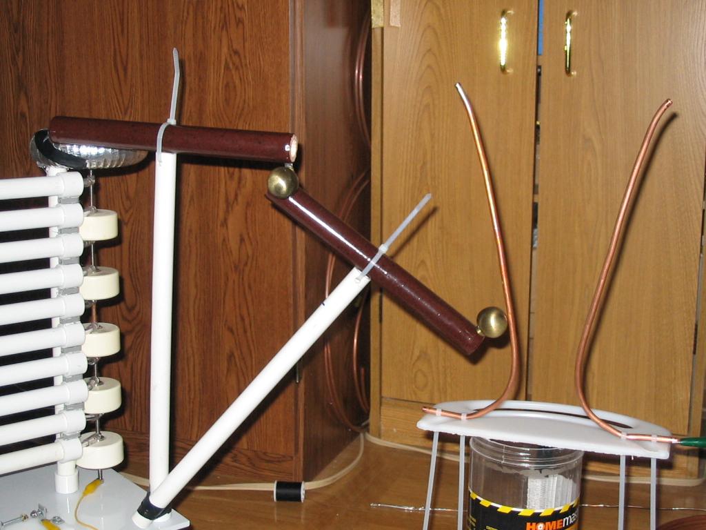
I chose to use these HV doorknob capacitors (40kv 2nF) for several reasons. Firstly, I think they look pretty neat, and are very robust physically. Secondly, I could use them as an integral part of the mechanical design. The capacitors are held together with threaded rod. The diodes are also connected to this threaded rod. While this technique worked well for my first 2.5-stage design, it was a bit "wobbly" for the full 5 stages. I then went back and glued some 1/2" PVC to the capacitors and diodes, yielding a rigid tower structure. When building ultra HV devices, you must build upward to get the desired voltage stand-off (think about tesla coils). Below are some pictures of the completed CW tower.
HV BALLASTING:
HV ballasting is required for 2 reasons. Firstly, directly shorting the output of a CW can damage the diodes from excessive peak currents. Secondly, I wanted to produce continuous arcs, and this requires some resistance so that the CW does not dump all its energy at once. So far my ballast has been a 100K ohm 200W ceramic body resistor, this is subject to change. The resistor needs to be physically large to stand off the voltage that will be "dropped" across it. My resistor is some 10" long and seems to withstand 80kv so far. The resistor is in the pictures above.
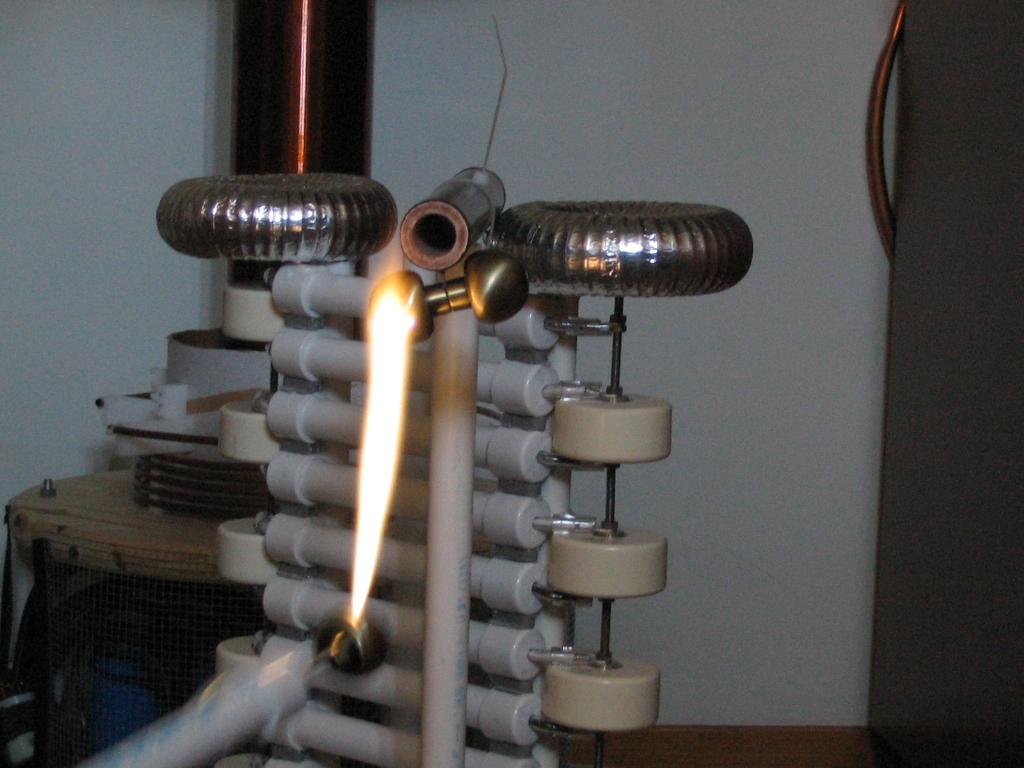
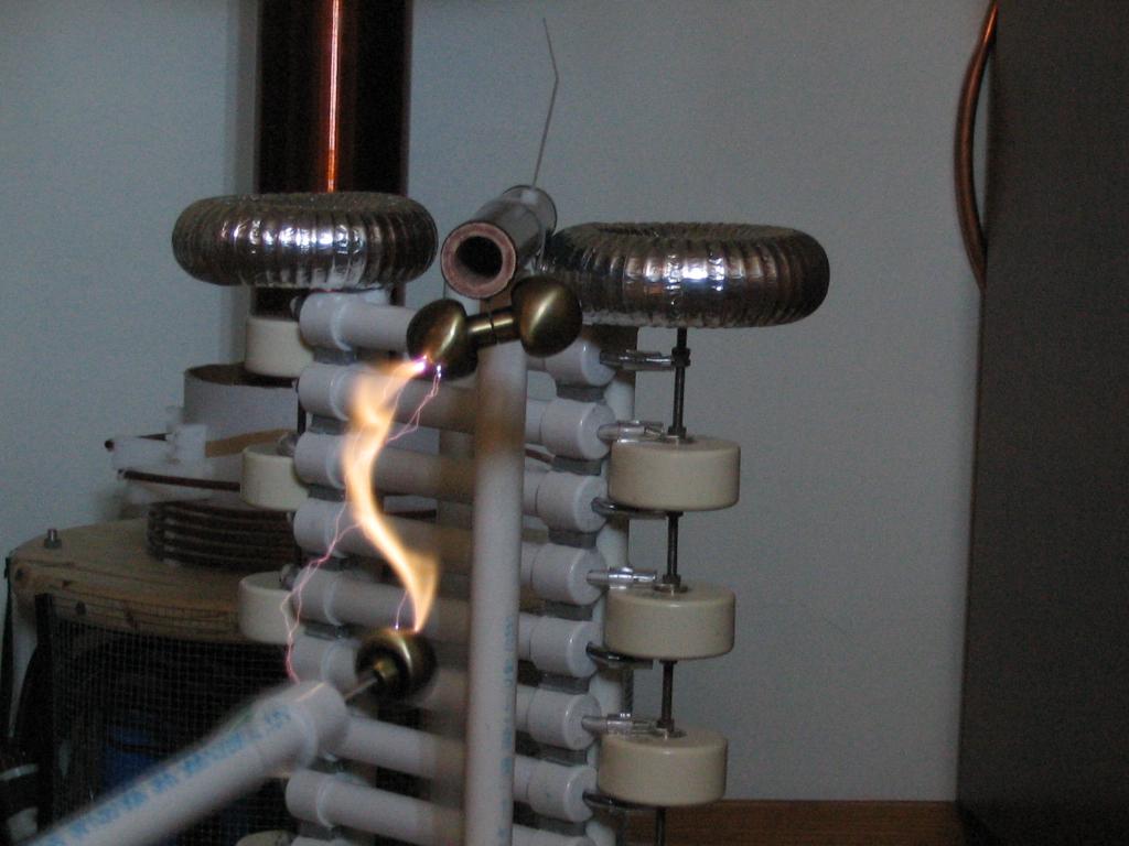
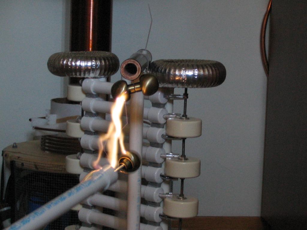
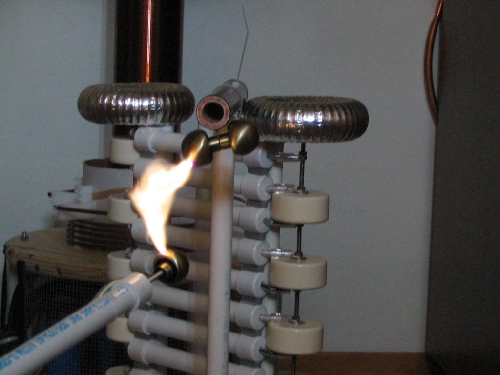
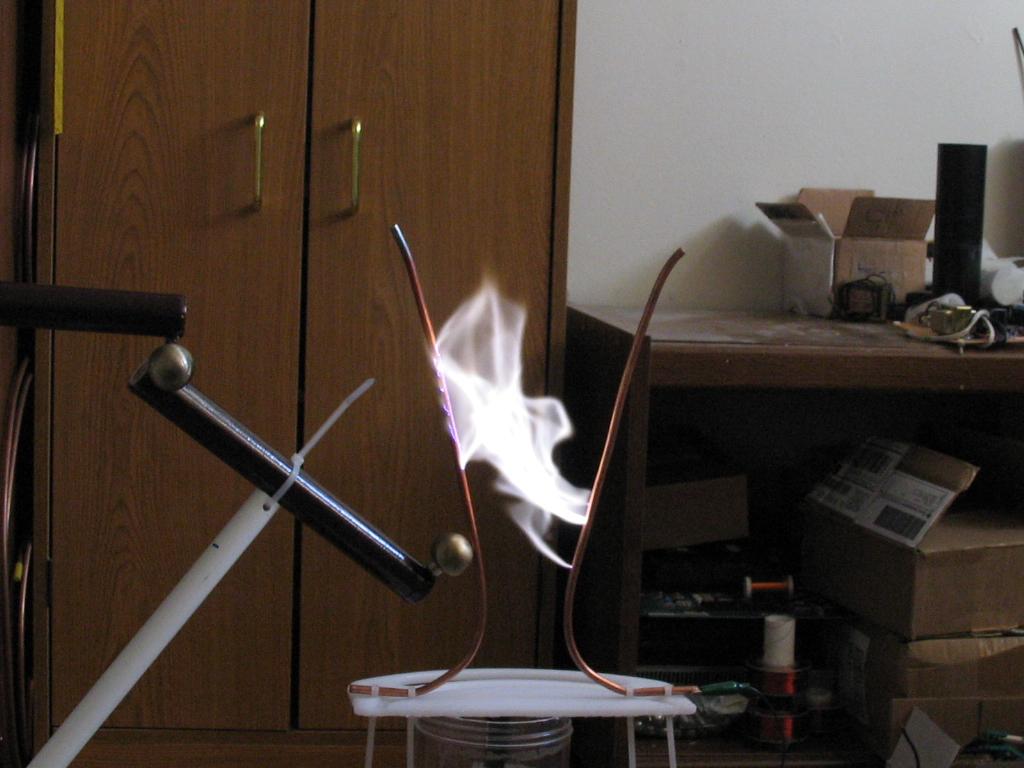
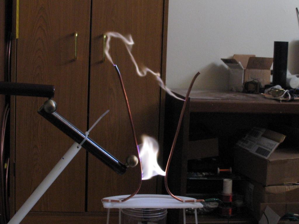
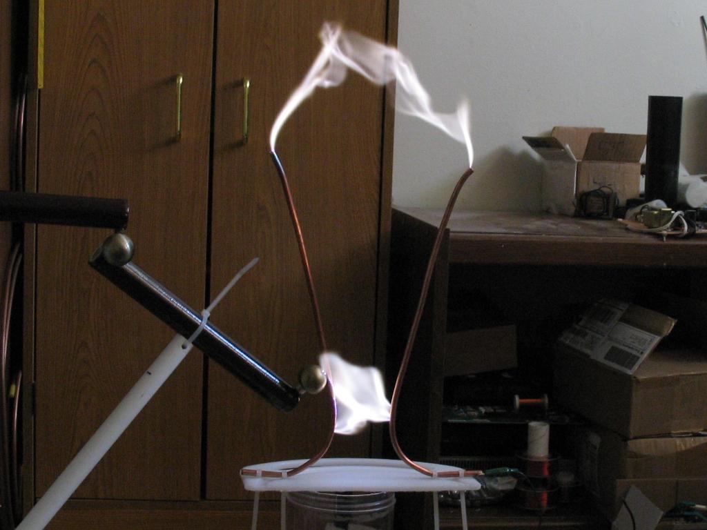
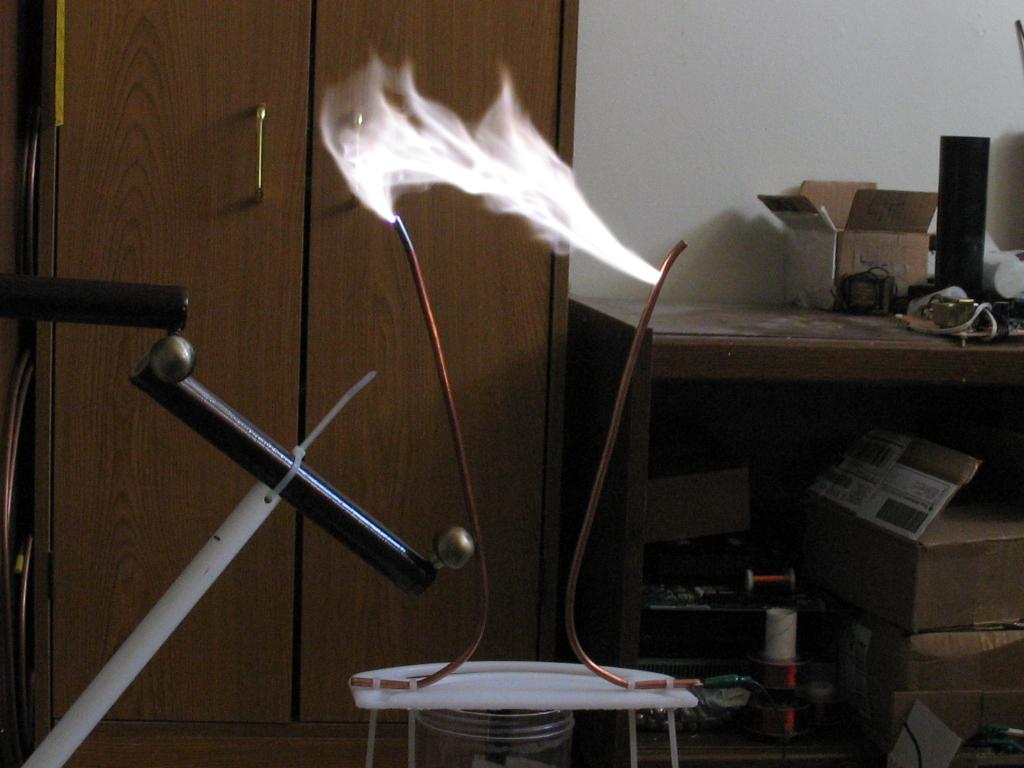
FIRST LIGHT (12/15/04)
This was the first time I got the CW to produce sparks that I was looking for. The sparks can start at about 4-5" between the 1" spheres, suggesting perhaps 80kv or more. When the arc strikes, it can be sustained as a ghostly yellow flame. The 1" spheres get incredibly hot, suggesting that there is quite a bit of current. I measured the input power to be 750W (which is not a whole lot) and it drops to about 2W when I don't draw sparks. My transformer starts to let out a whine at 800W, I'm not sure why, but I know it's not good.
An interesting thing to notice is that in some pictures there are only some thin purple sparks. This occurs because of the sharp points on my ground electrode, behind the sphere on the end. These thin sparks are some 8" long, but do not allow for a continuous arc. When an arc is started, it can be drawn out to about 7" or so.
 Here
is my quick lashup. You can see the H-bridge and driver on the left,
transformer in the middle, and of course the CW stack on the right.
Here
is my quick lashup. You can see the H-bridge and driver on the left,
transformer in the middle, and of course the CW stack on the right.


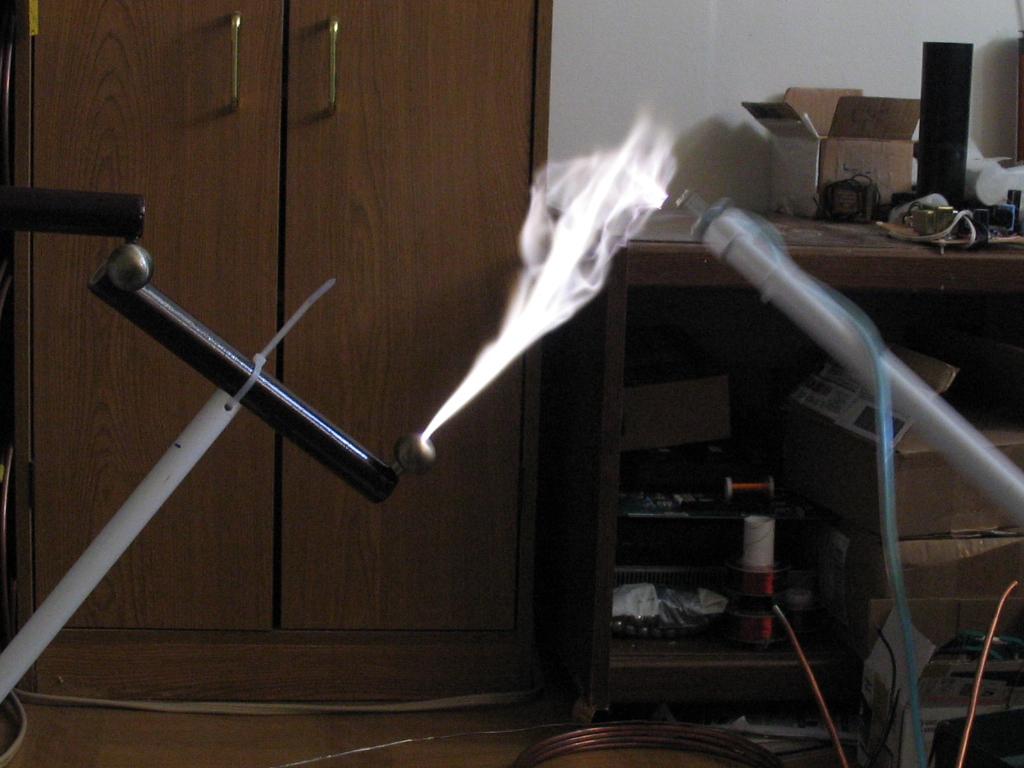
SECOND LIGHT (12/23/04)
I made a few changes to my setup. Firstly, I reduced my primary turns to 17 turns to get more V/turn on the transformer, hoping for higher output voltages. I think I havent even gotten much over 7kv or so out of the transformer so far. I then also built a voltage doubler to give me a maximum of about 400VDC on the bridge, assuming a very light load. I then also added an air gap to my transformer core, to avoid the risk of saturation. I also thought the core would increase the leakage inductance enough to limit my input power to a reasonable level, but that just isn't so! I managed 1800W of real power from the 120V line into the CW driver! This was achieved at around 300VDC input. The output at this voltage should be around 90kv unloaded from the CW. I'm not sure if I am actually getting that much voltage though. Anyway, this thing is pretty fun for making big arcs. I attempted to power a lifter with it, and it did work until an arc set the lifter on fire. I need several MEGs of output resistance to do more lifter work with this thing.
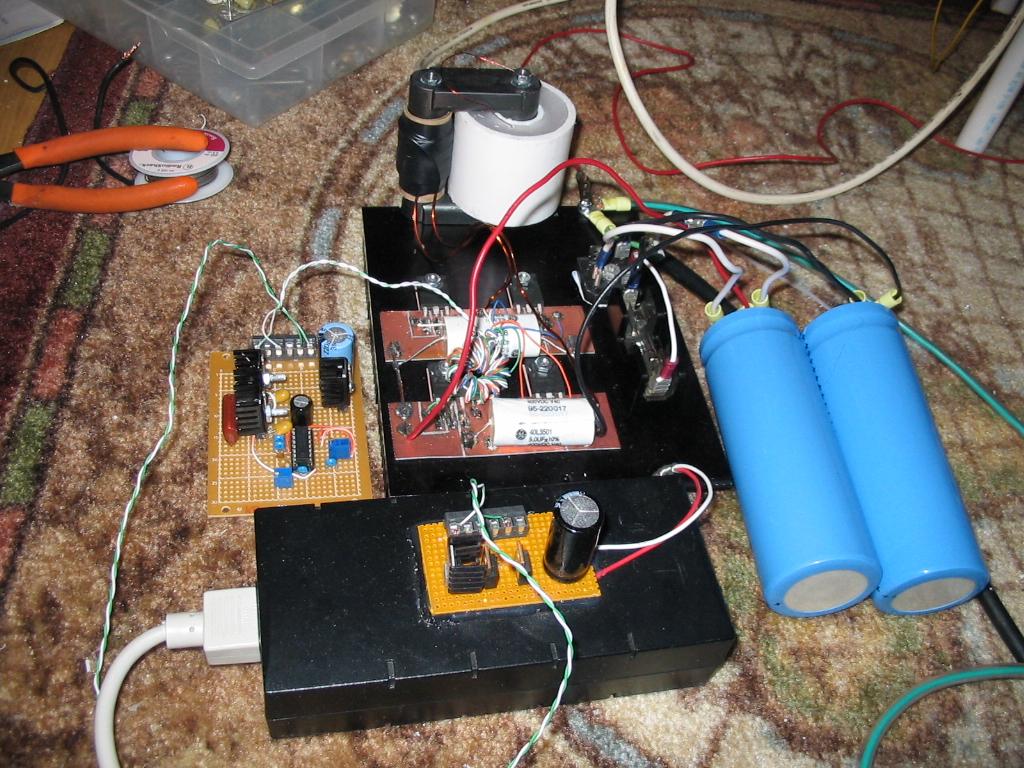 Here
is the latest setup for my CW's power supply. Transformer mounts nicely on
the heatsink. The second lytic is for the voltage doubler.
Here
is the latest setup for my CW's power supply. Transformer mounts nicely on
the heatsink. The second lytic is for the voltage doubler.
 Here
are the 2x 100K 200W limiting resistors. I really do need more resistance,
but they will work for now.
Here
are the 2x 100K 200W limiting resistors. I really do need more resistance,
but they will work for now.

Here is a short video clip of the CW in action (3.8MB .AVI)