DRSSTC-3
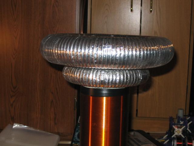
After building my first DRSSTC-1, and then my giant DRSSTC-2, I wanted something more portable for demos. I realized at the time that even a small DRSSTC should work very well and be quite impressive for a given size. When I first built this coil there were a few different things than there are now. Firstly, I used my older DRSSTC controller which was very basic and does have some minor flaws that the new controller takes care of (more on that below). Secondly, the MMC consisted of only 2x .15uf 2kv film capacitors in series for 75nf at 4kv. This in fact worked very well, but the caps would get quite hot. In fact I made several attempts to destroy the 2-cap MMC, but could not!! Eventually I decided I should be using a larger bank of capacitors, just to make my setup more reliable (keeping demo's in mind). I also now use a nicer looking toroid than my old elbow duct one. All pictures presented are updated (edit: well, they were up to date) and I do not plan on having any older pictures posted (this avoids much confusion).
Specs on this coil:
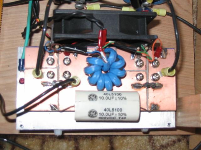
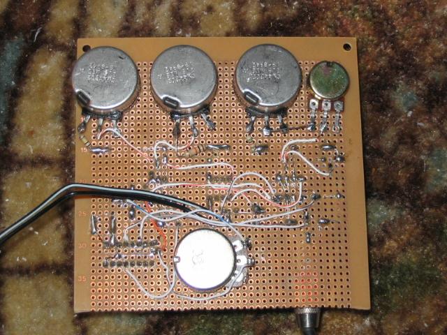
| Power Electronics | Half-bridge of 40N60 IGBTs (Fairchild) protected by 440V TVS and a 10uF film capacitor. 350VDC comes from a voltage doubler and 2 x 2900uf 200V electrolytics. |
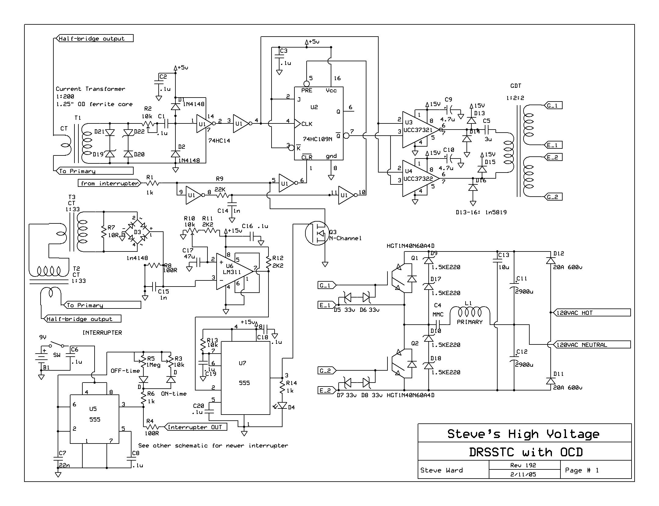
| Control Electronics | Primary current feedback setup using a 74HC14 to receive and square up feedback. A 74HC109 J-K flip flop synchronizes the interrupter signal and feedback signal to avoid turning the coil off during a RF cycle (see schematic). |
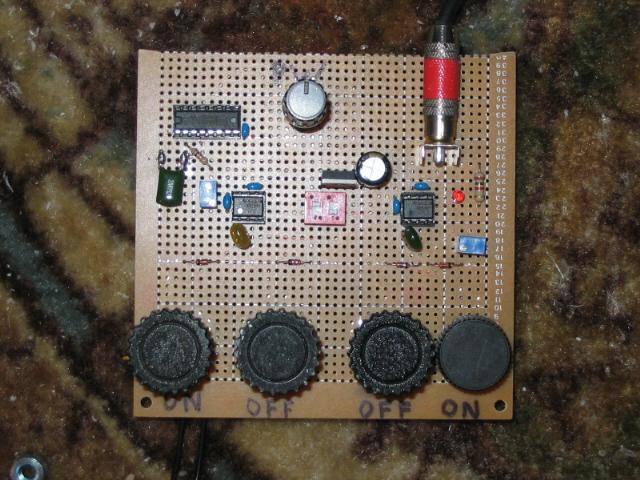
| Interrupter | Normal operation as well as Burst Mode operation. |
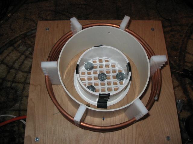
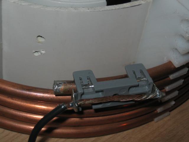
| Primary | 5 turns of 1/4" cu tubing, 8" diameter, .20" spacing. |
| Tank Capacitor | 2 strings of 4 series .15uf 2kv 942C series capacitors made by CDE. Total rating is 75nF at 8kvDC. |
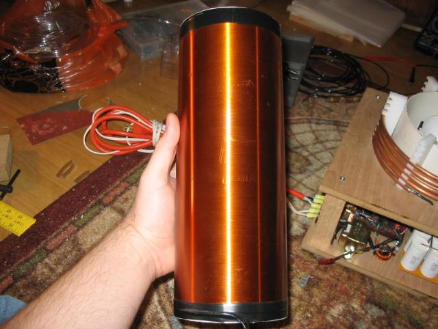
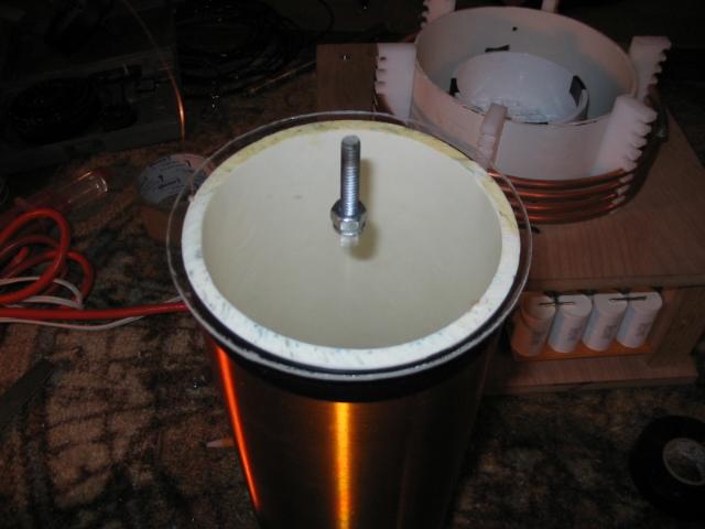
| Secondary Coil | 4.5" diameter, 11" long winding of 30awg magnet wire. 2 coats of polyurethane varnish. |
| Toroids | Latest toroid is a 4"x13" spun aluminum toroid from John Freau. |
| Spark Length | 37" is my best spark length so far. |
Main Schematic (updated 2/11/05):
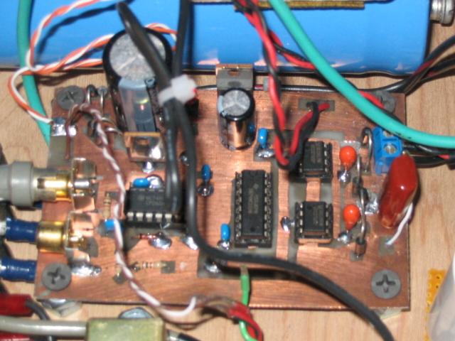
Construction Photo's:


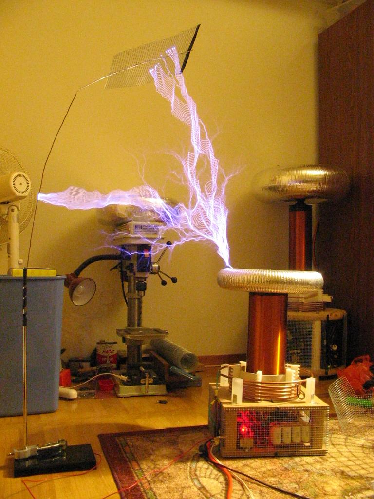
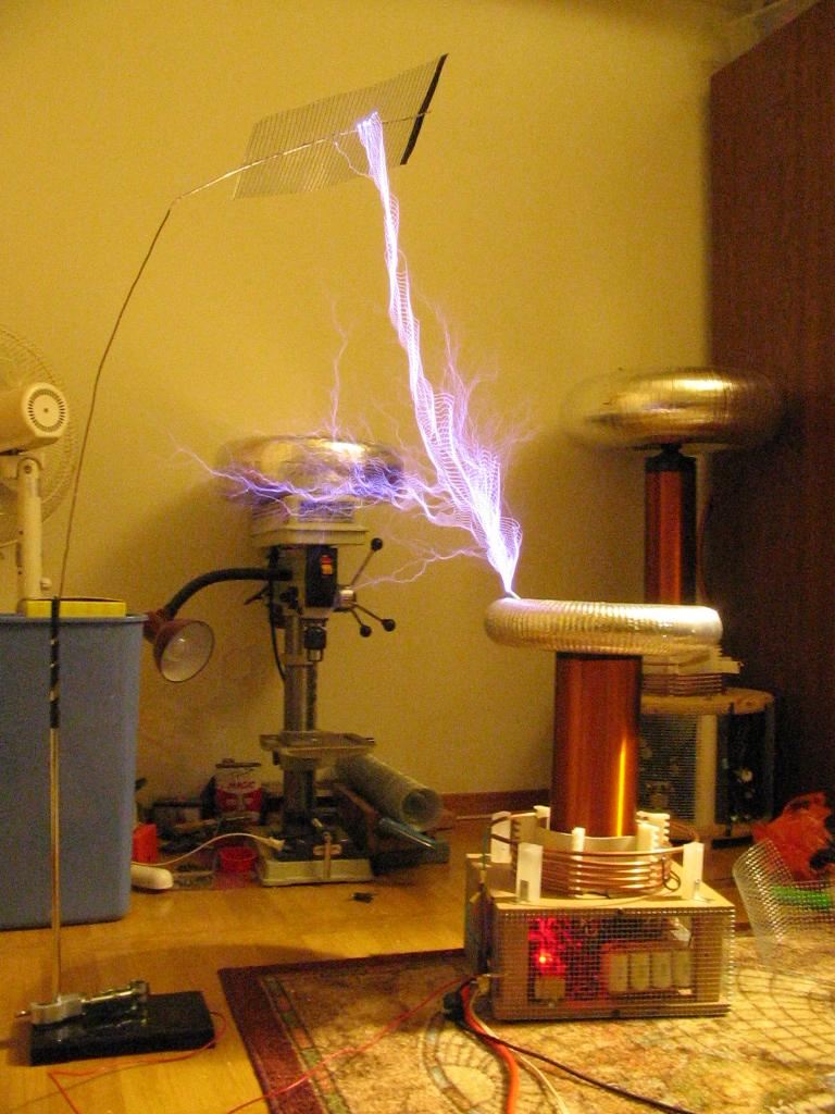
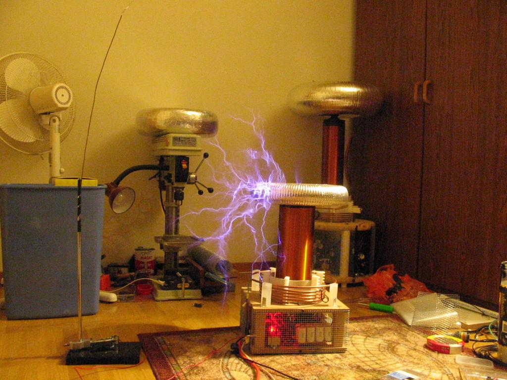
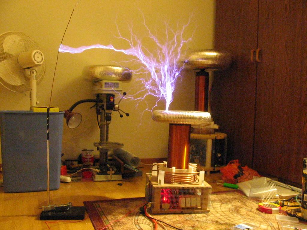
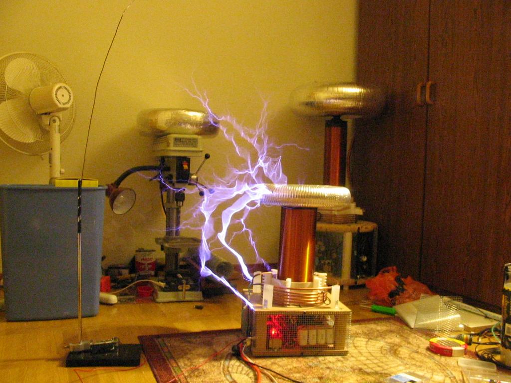
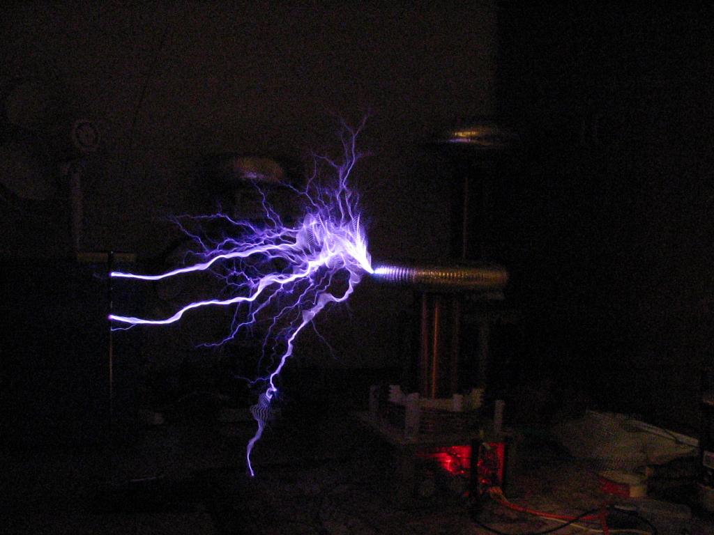
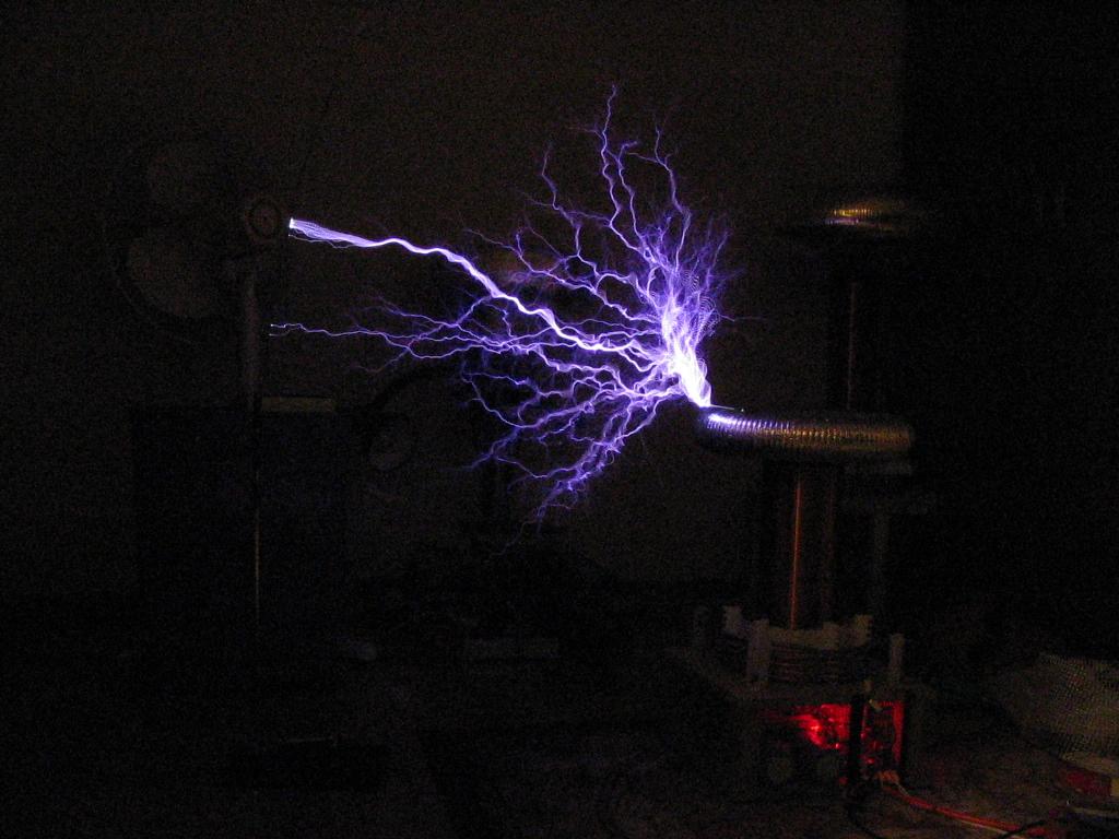
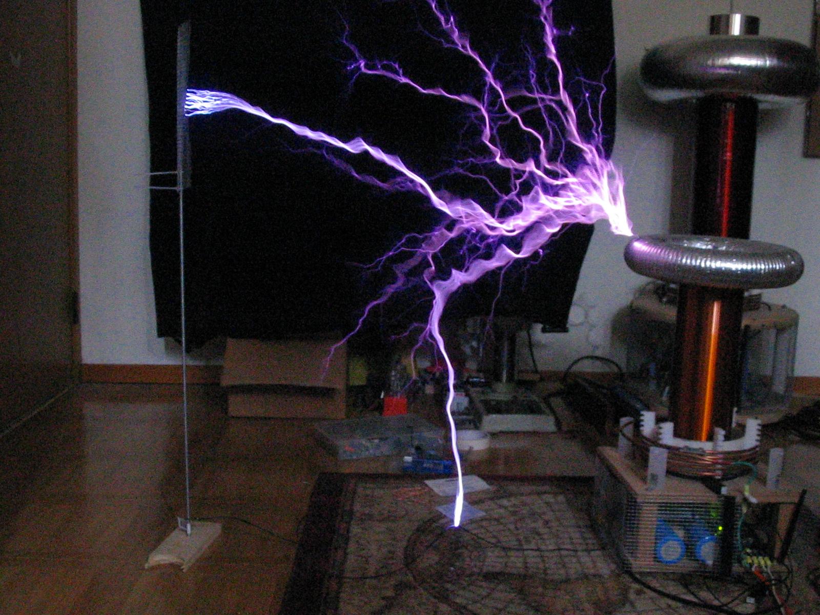
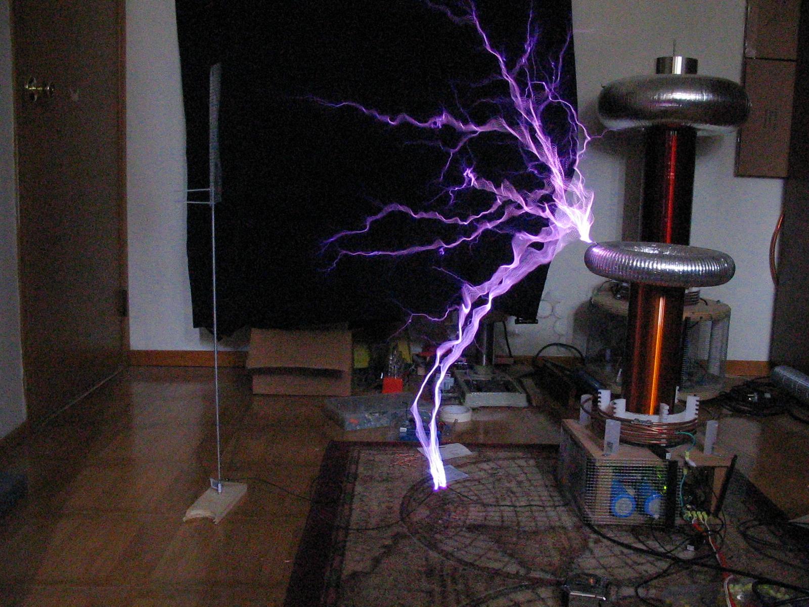
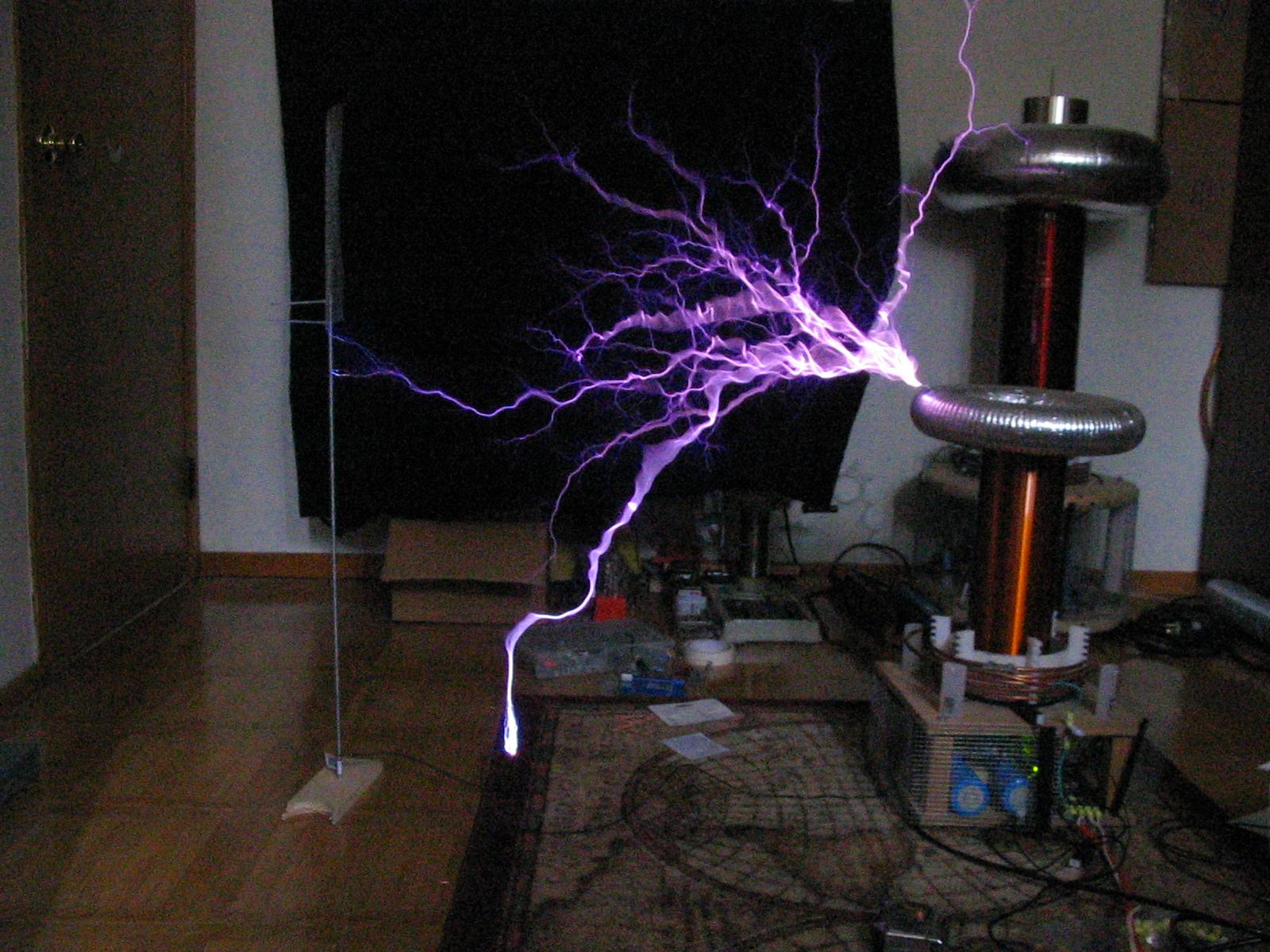
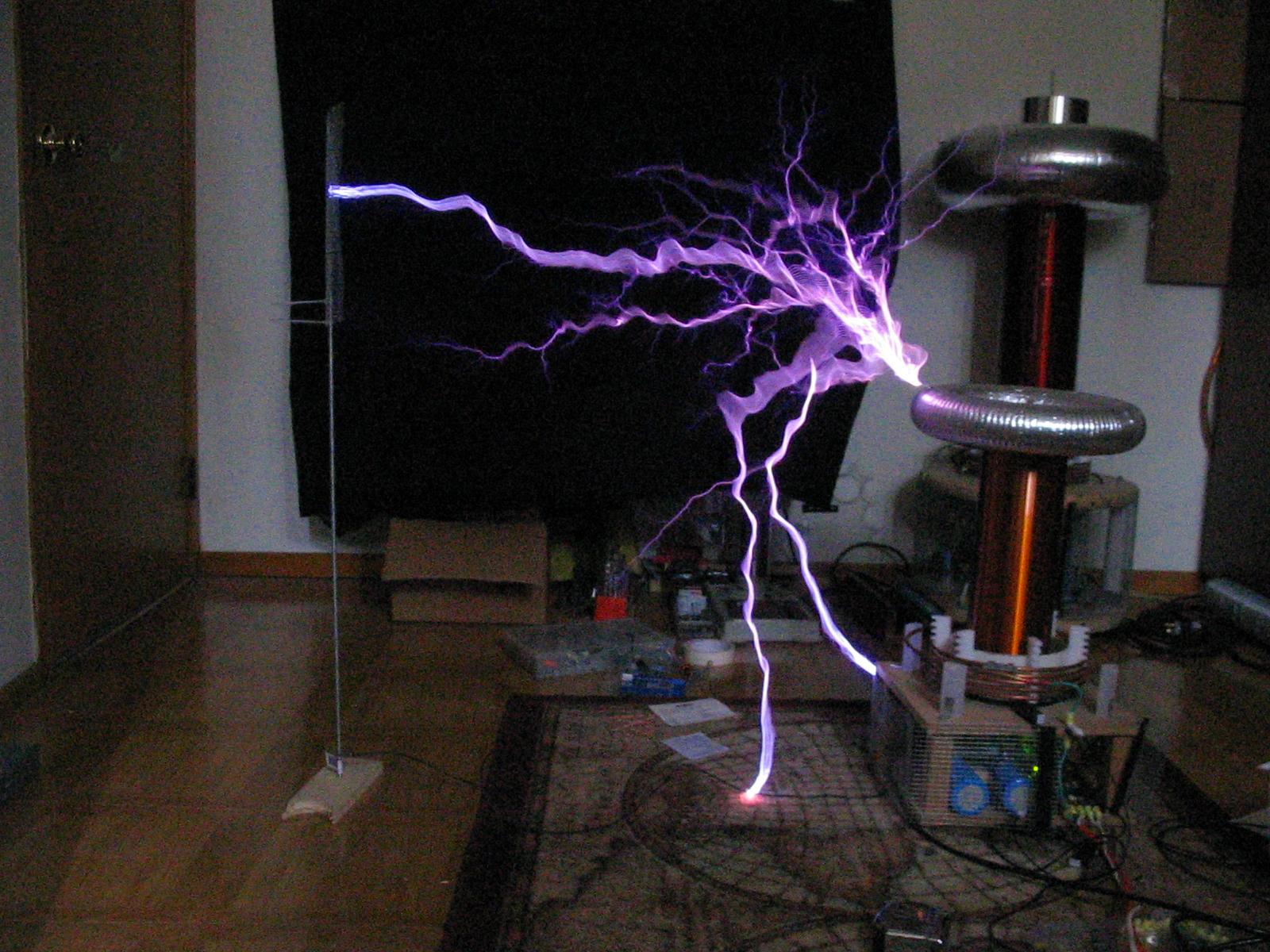
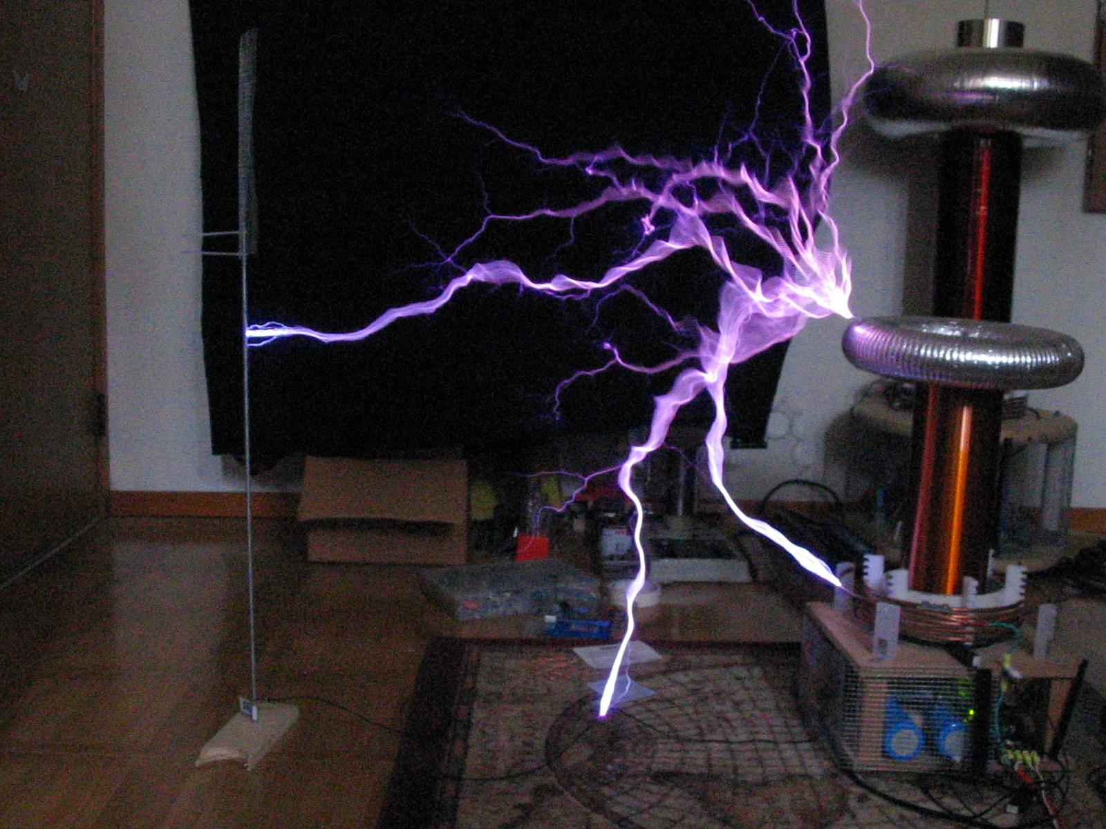
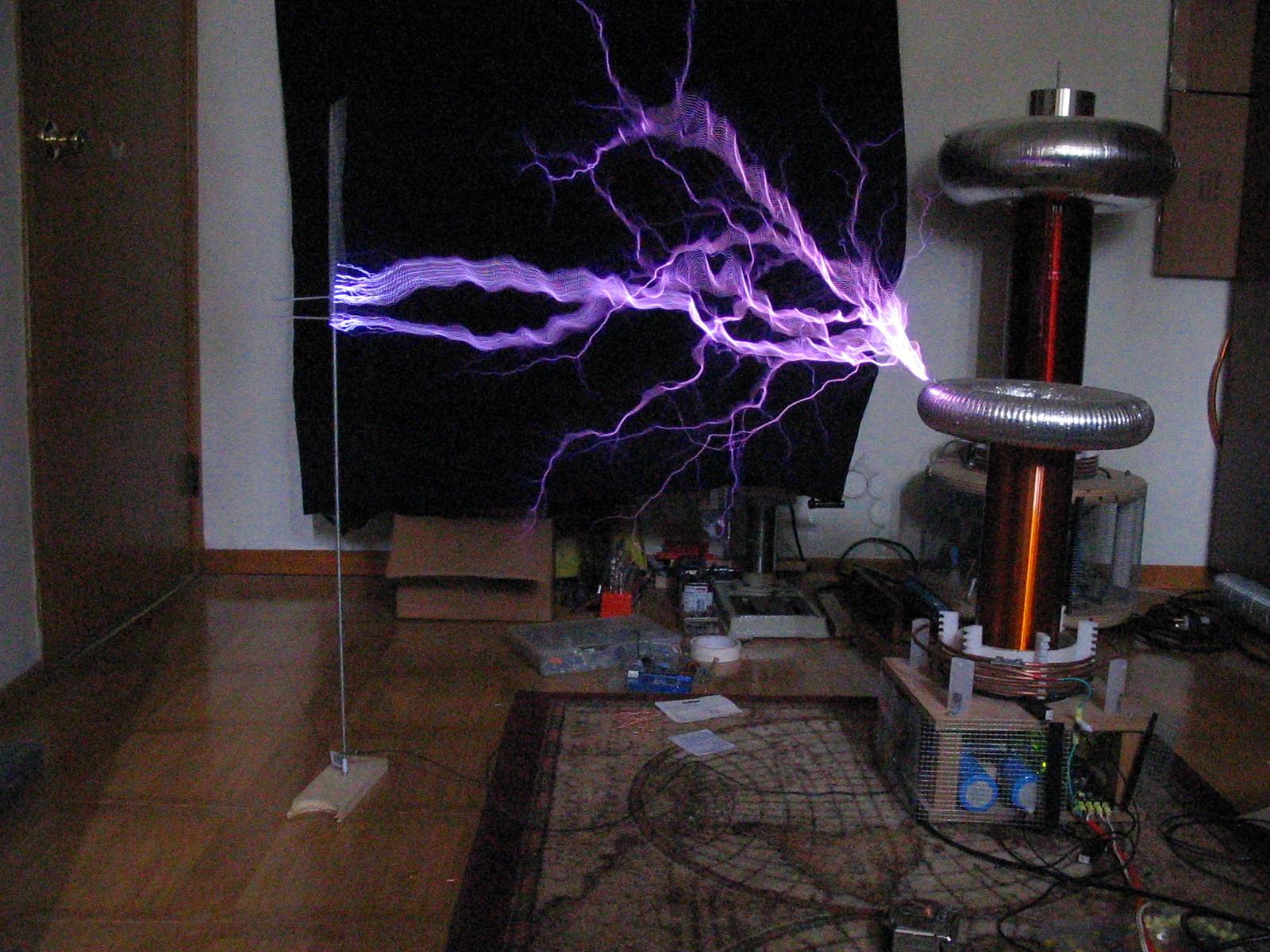
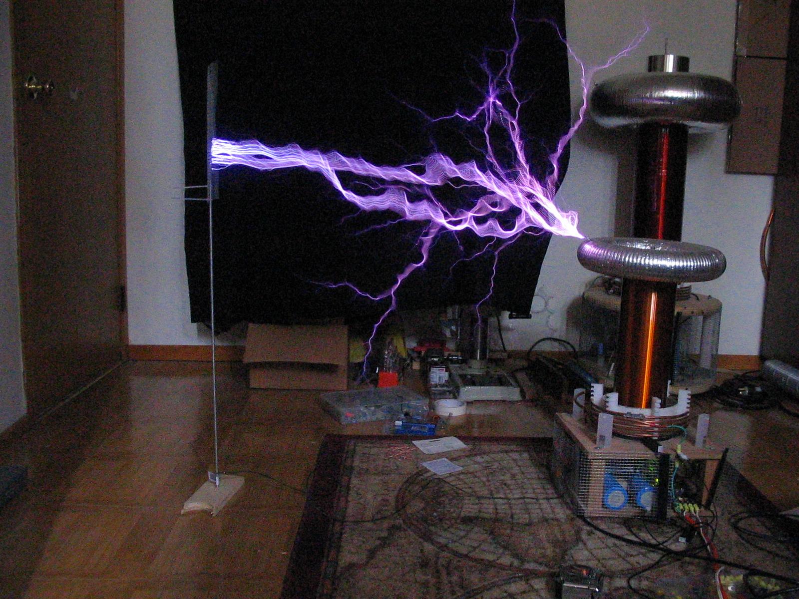
Spark Pictures (spark length set to 22"):
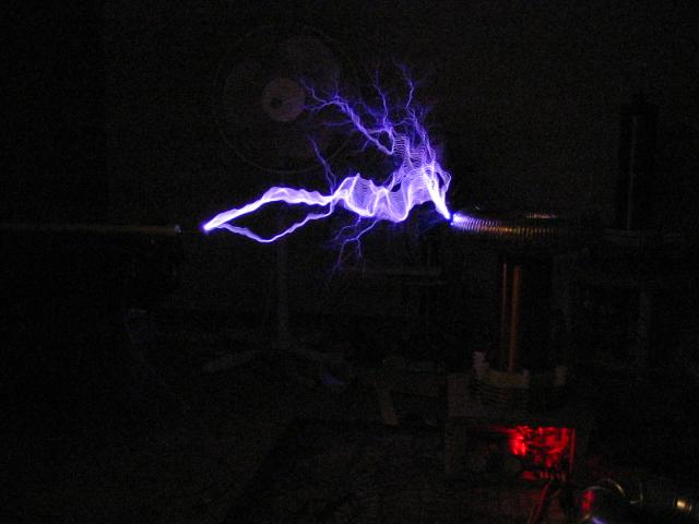
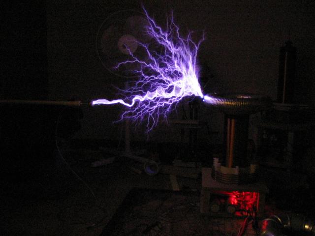

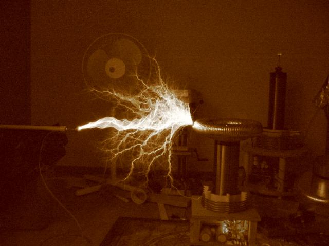
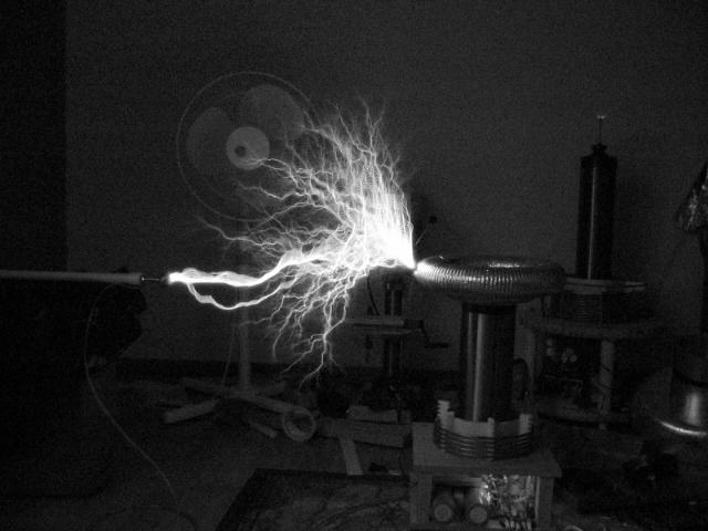
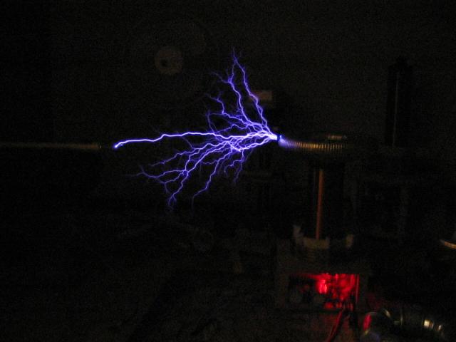
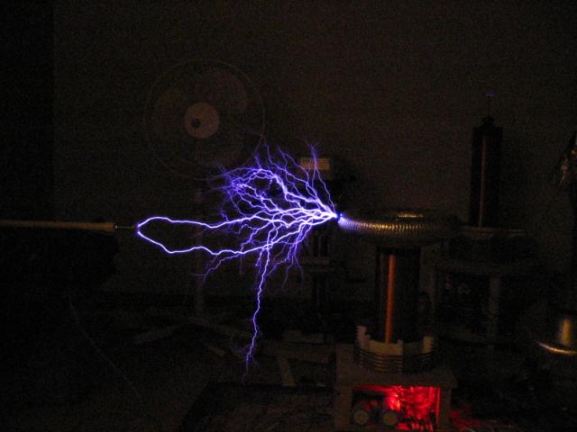
A few interesting things to note. Firstly, look at the secondary in the background, it has corona spraying off of the top! Second, the last 2 pictures are of burst mode operation where each "burst" produces its own streamer, and then another streamer starts with the next burst, but at a different and random place.
UPDATE: 12/12/04
One of my leading causes of IGBT failure was a spark hitting the primary or the control electronics below the coil. So I bought some screening (23awg, 1/4" squares) and put that around the base of my coils. Interestingly, I found the performance to increase. I can get constant power arcs to 24" and a few strikes near 30". Before 24" was somewhat rare. Here are some pictures I took tonight... I may try to get some better ones later, but these are pretty good.
UPDATE: 1/22/05
I built and calibrated a current transformer today, so of course I had to immediately start doing tests! Here is the raw data, it does suggest that shorter ON periods are desired for highest efficiencies. More on my "theories" later...
|
Ipk (tank) |
%Vin (of 140VAC) |
Burst length (uS) |
BPS |
Watts |
Spark Length (inches) |
|
260 |
59 |
200 |
120 |
284 |
20 |
|
280 |
61 |
180 |
120 |
269 |
20 |
|
300 |
62 |
160 |
120 |
240 |
20 |
|
310 |
64 |
140 |
120 |
212 |
20 |
|
320 |
67 |
120 |
120 |
197 |
20 |
|
360 |
75 |
100 |
120 |
182 |
20 |
|
400 |
87 |
80 |
120 |
170 |
20 |
|
400 |
92 |
70 |
120 |
161 |
20 |
|
400 |
100 |
60 |
120 |
135 |
20 Not Met |
|
|
|
|
|
|
|
|
450 |
100 |
100 |
120 |
329 |
25 |
|
440 |
90 |
120 |
120 |
344 |
25 |
|
400 |
81 |
140 |
120 |
339 |
25 |
|
390 |
80 |
160 |
120 |
399 |
25 |
|
350 |
78 |
180 |
120 |
437 |
25 |
|
330 |
75 |
200 |
120 |
454 |
25 |
|
|
|
|
|
|
|
Note that these tests were performed with secondary base feedback.
UPDATE: 2/11/05
After reading about Terry Fritz's DRSSTC work on the TCML, I decided I really liked the idea of primary current feedback. You will see that the schematic above is new and reflects the changes as of this date. It is crucial to use an over-current detector (OCD) when using primary current because the primary current will ring up excessively high if the secondary does not pull enough energy out of the primary (if you are out of tune, if the coil is not making sparks, or if you get heavy ground arcs). The OCD uses 2 CTs cascaded to get roughly a 1:1000 ratio. Cascading CTs is usually a bad idea (EDIT, i was wrong, see later updates) because it can add phase shifts etc, but in this case where we are just watching the peak current, we don't care if the CT's output is slightly delayed. Anyway, the LM311 pulses low when the negative input exceeds the positive input. This negative output pulse triggers the 555 which then spits out a 1mS pulse which in turn drives a MOSFET which then pulls down the interrupter signal... phew! It also lights up an LED which is a nice visual indicator that its working :). Q3 (the MOSFET) can be basically any small MOSFET rated for 15V or so, don't care about the current, its only a few mA.
A few other new changes in the schematic. Notice that I am using 15V zeners to clamp the output of the CT directly. The 1n5819 schottkey diodes take care of the zeners slow recovery time. Before the CT was not really loaded properly, and this caused some problems when running primary current (much higher output voltage on the CT in this case!). I had to make a new CT for the primary current feedback. This new CT was on a larger core and uses 200 turns of 30awg wire. Note that I completely got rid of any gate resistance that I had before. Its very important that you check for cross-conduction of the IGBTs if you choose to follow my design! I also changed the flip flop circuit slightly (notice the !PRE). Before I had to feed a portion of the interrupter signal into the feedback input to make the clock input change state, and get the thing oscillating. This new method causes the flip flop to reset about 15uS after the interrupter pulse has gone (assuming there was no clock input on that pulse). This in turn will set the flip flop to another state so that when the next interrupter pulse comes, the output changes state. Hope that makes some sense!
Some interesting things I noticed with the primary current feedback. Firstly, I have tried 2 tunings so far. The first is tuning the primary to somewhere between the upper and lower pole (f1 and f2). In this tuning, the primary current appears to bounce between f1 and f2 and eventually reside at either f1 or f2 (not sure which). This seems to work ok with high coupling between the coils. The second tuning is tuning the primary to the lower pole (f2). In this method the streamers growth actually brings the system into better tune, causing even greater growth. Downside is that it takes about 60% input power before much output is achieved. Lower coupling is required to keep the secondary from arcing down the coil to the primary. I achieved 30" horizontal sparks with this type of tuning, and I believe with further fine tuning I can get even more. The primary tuning is *quite* critical with primary feedback as I am finding out but I do think this is quite manageable. Primary current feedback does have the main benefit of ZCS, so I think that's worth while :).
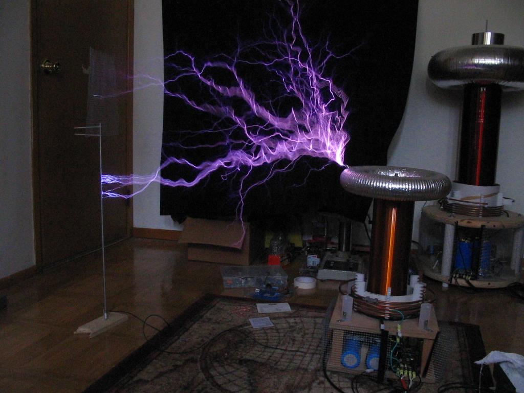
UPDATE: 2/14/05
Here are some pictures of it running off primary current feedback. The ON time is 110-140uS, at BPS from 120-240. Wattage ranged from 400-600W. Primary current was reading about ~420A on the scope, *almost* perfect ZCS... there is about a 300nS delay it looks like (apparently it does not matter too much). Distance to the target is 32" (yeah, it works ;-)), and some of the floor strikes are 30-32". The coil arcs to the target at least once a second if not more. I really need to take pictures when it's darker in the house, the sunlight getting in through the window detracts from the details that the camera should be able to pick up. Enjoy :-).
Here is a VIDEO of the coil in operation (3.9MB .AVI).
UPDATE: 3/9/05
I should also mention a bit about current transformers. I read a
paper that basically said, for RF use, cascaded (1 CT feeds the next CT) CTs are
better than a single CT with lots of turns on it. This makes life much easier!
For my DRSSTC-1 using primary feedback i use 2 cascaded CTs, each a 1:33 ratio.
I use an identical set of CTs for the over current detection. It seems to work
great. One other bit of crucial information. Terminate the CTs (either it be the
diodes on the feedback CT or the resistor on the OC CT) as close to the board as
possible (i mount the resistors/diodes right on the PCB). This greatly helps
reject noise on both circuits.