DRSSTC-.5
Updated 11/23/2008
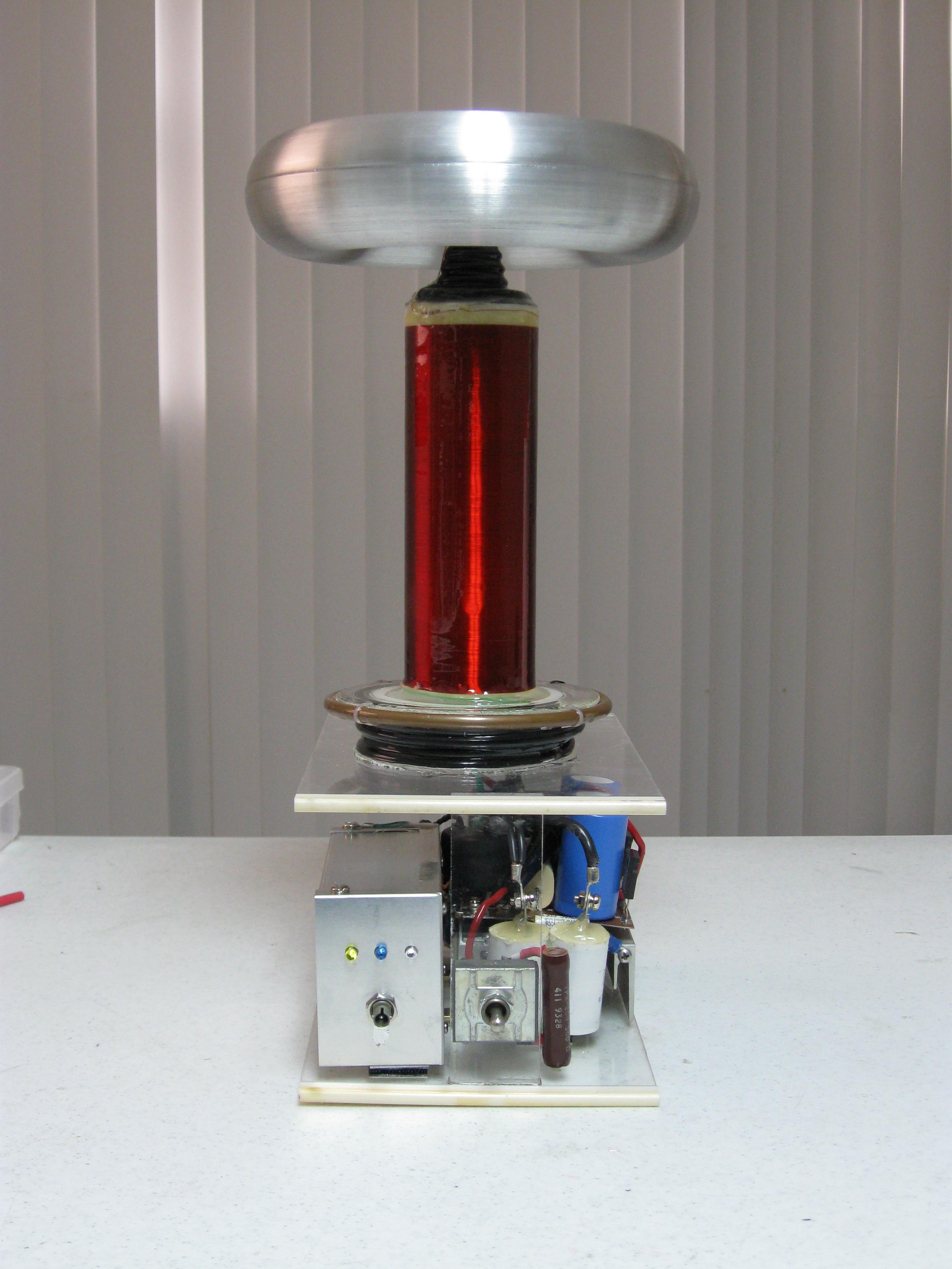
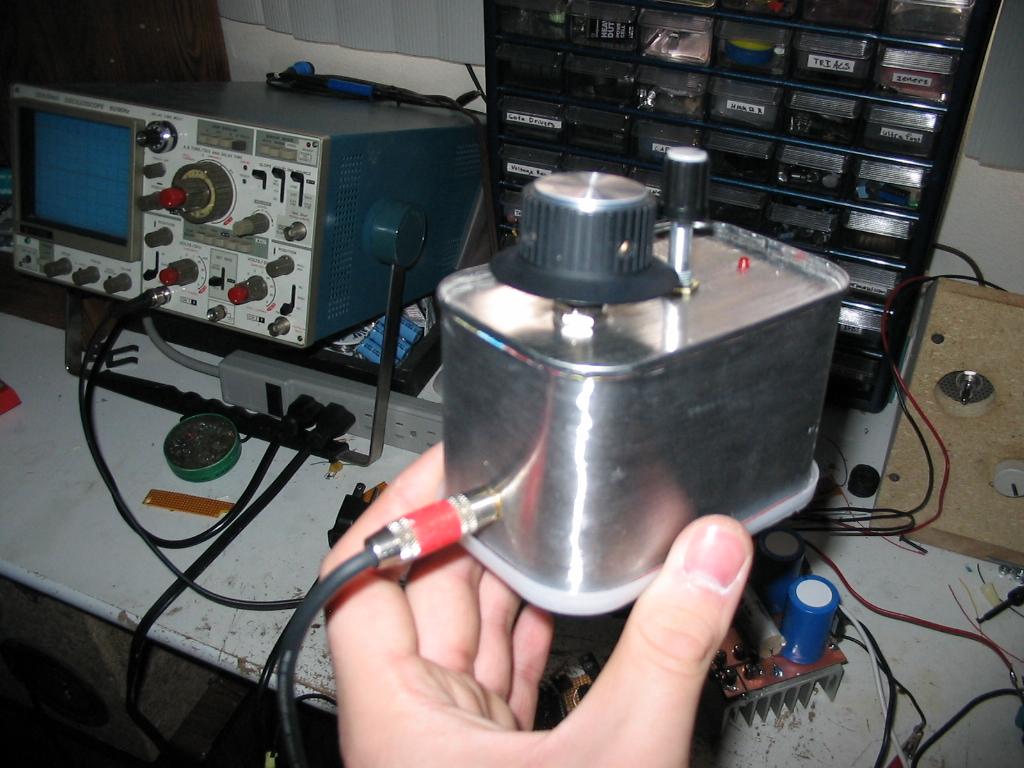
While this is actually the 4th DRSSTC I have constructed, I'm calling it the ".5" to signify its very small stature. The goal for this project was to see how small I could make a DRSSTC, but still maintain a respectable performance. Also, I was tired of lugging the variac box around, so I decided this coil would have a new method for controlling power. Basically I can sweep the interrupter's ON time from about 1us to 120us, thus controlling the streamer length. I also used a timing pot with a built in ON/OFF switch, which controls the coil just fine. As of now, this coil makes 18" sparks to a metal target, which is great considering its dimensions. Below are the pics and specs for this coil (with current updates):
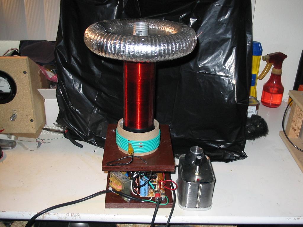
Secondary Coil: 2.5" OD PVC tube, 7" long. 36awg magnet wire wound a length of 6.5". Fo (unloaded) is around 620khz.
Toroid: A single 8"x1.5" toroid drops the Fo to 350khz.
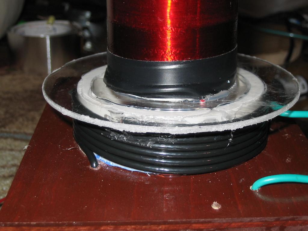
Primary: 4.75 turns of 8awg THHN on a 3.5" PVC form.
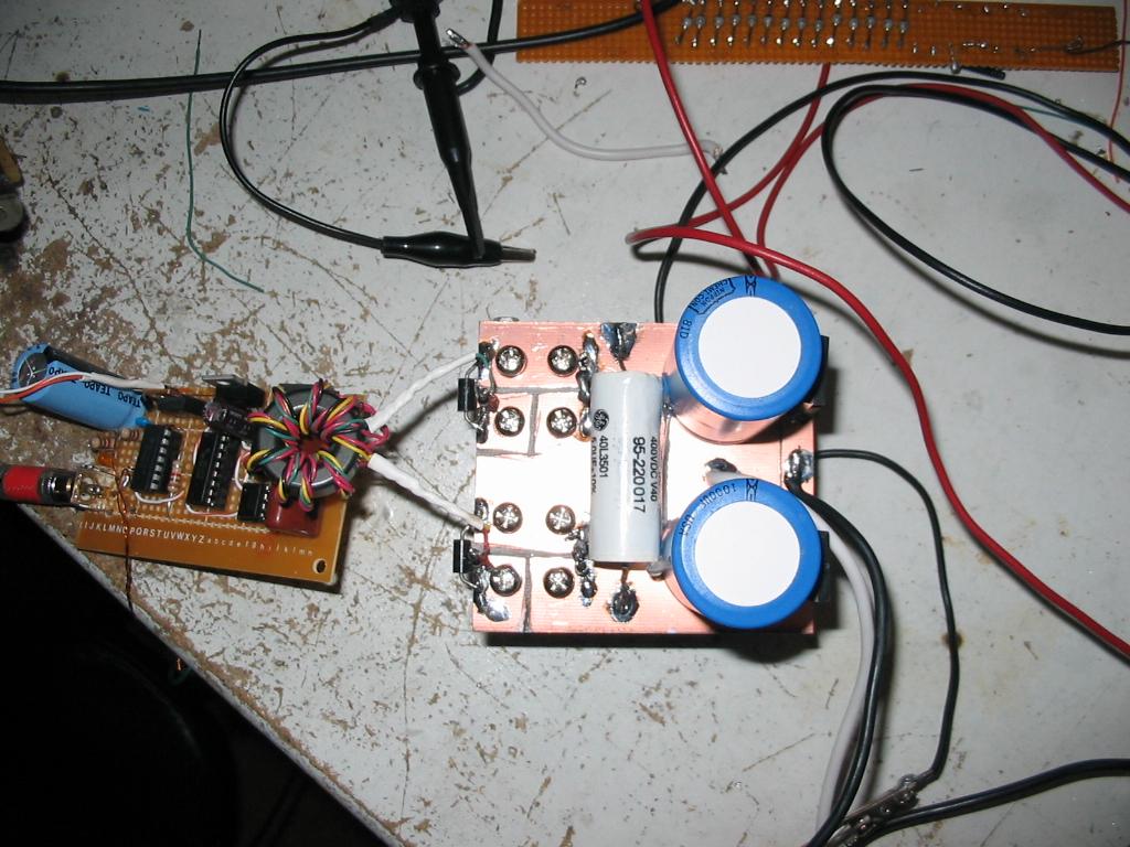
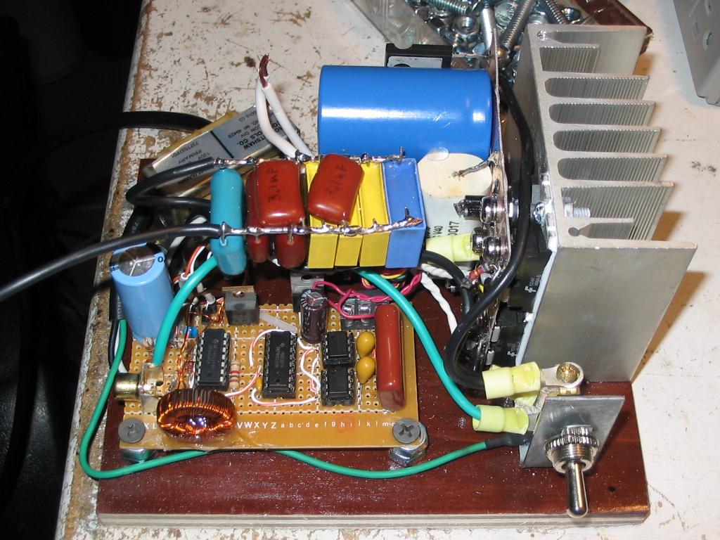
Tank Capacitor: 2 series .15uf 2kv foil/film caps made by CDE. 75nf 4kv overall rating.
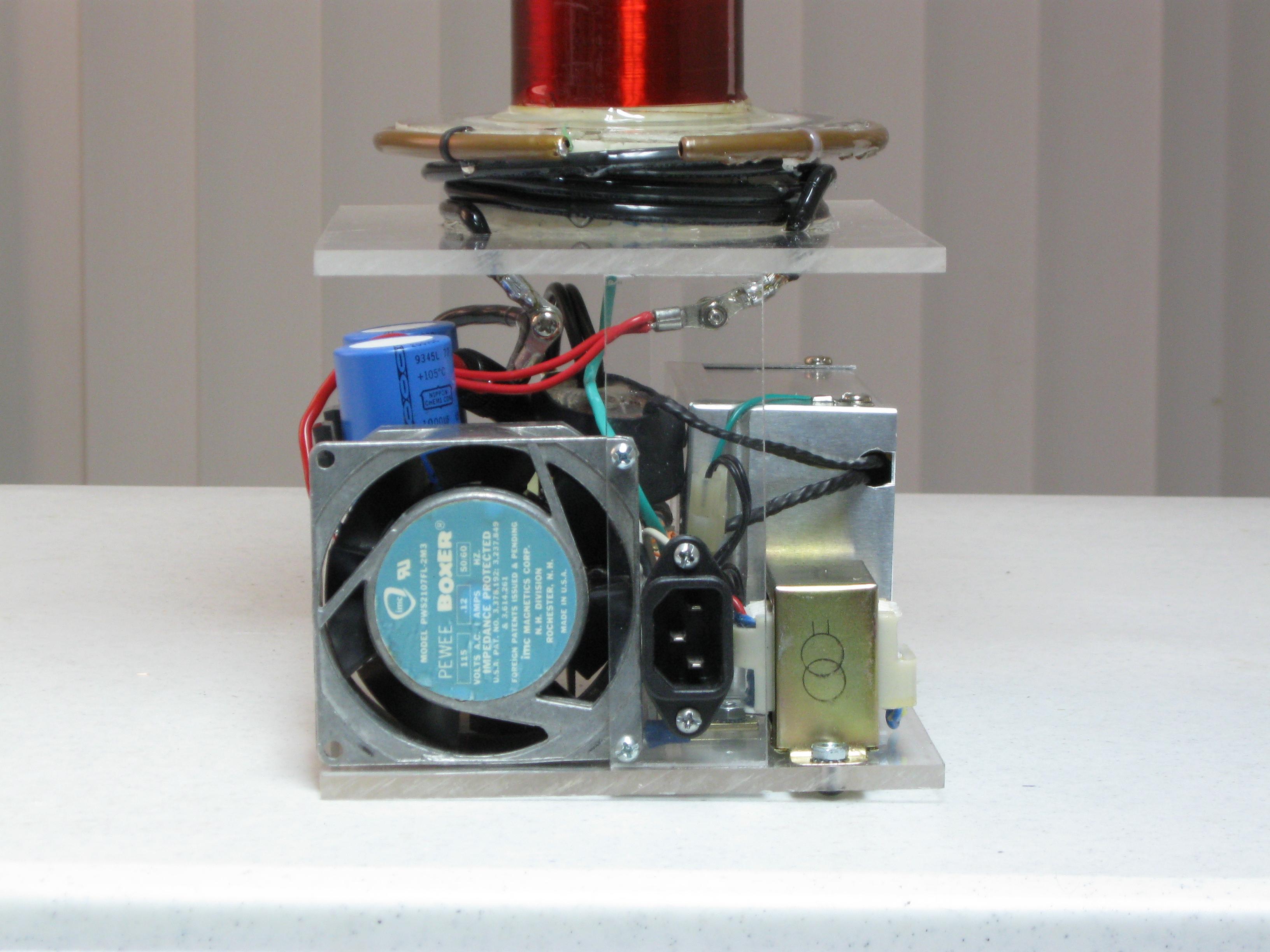
Power Electronics: Half-bridge of my favorite IGBTs (40N50), 2x 1000uf 200V lytics make up a voltage doubler for 350VDC.
Control Electronics: My new universal driver.
Spark Length: 18" horizontally point to point at a measured 180w.
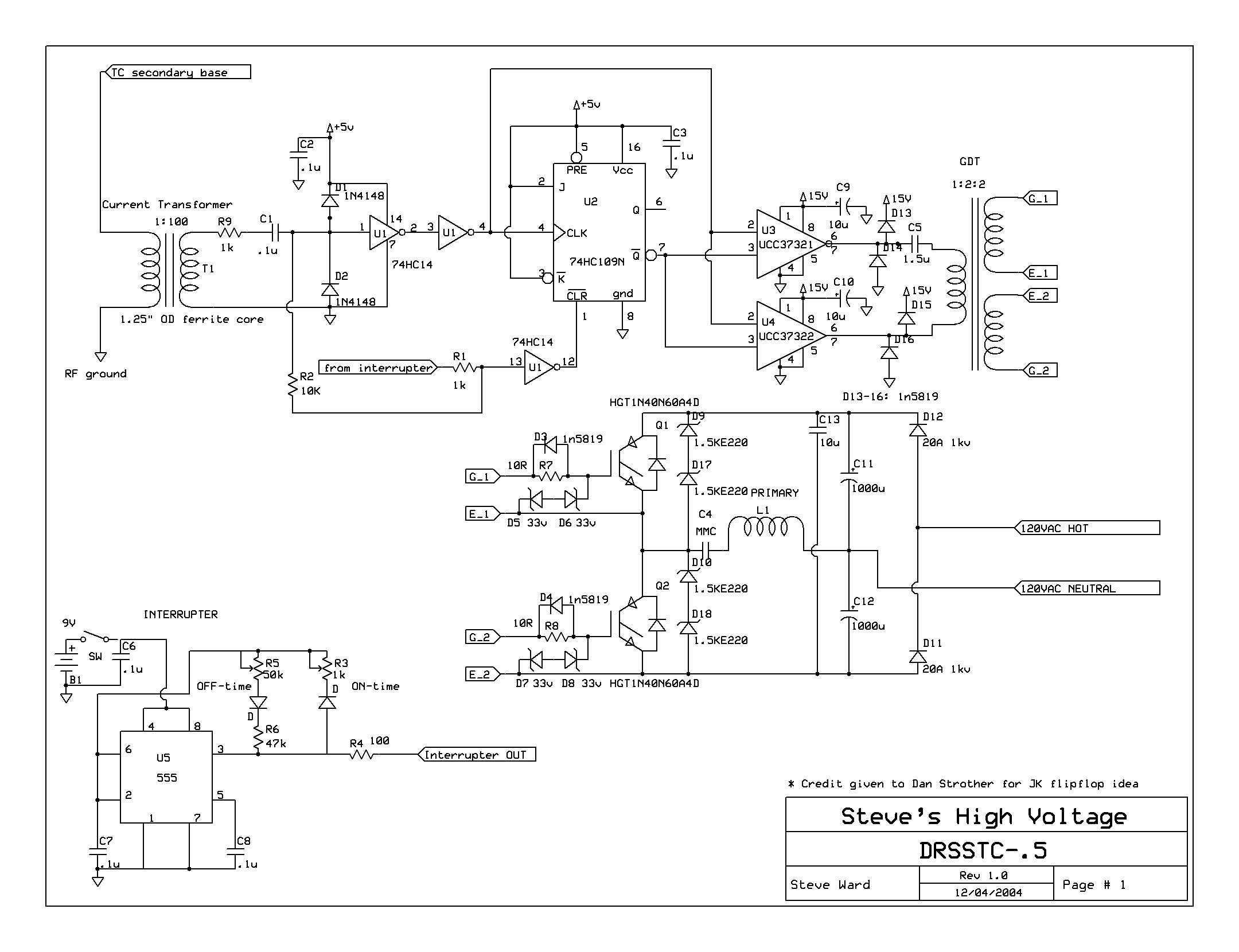
Schematic: For historic purposes, this was the original driver. I suggest using my new driver.
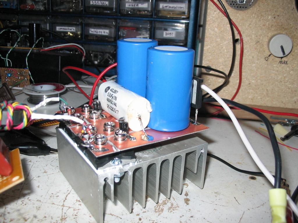
A few interesting findings. Firstly, its extremely helpful to have plenty of filtering on the Gate driver chips, without some large capacitance there I had issues with the gate voltage falling down to 15V when it should have been at 30V, not to mention awful looking waveforms. Adding a 470uF lytic (in addition to the 10uF tantalum capacitors that were already there) across the drivers helped greatly. I also found that lowering the coupling actually lengthened my sparks considerably! This and the addition of an extra 16nF (I started at 34nF) of tank capacitance increased my spark length by 40%.
An update: apparently those small PP caps I used for the MMC (the old MMC was made up of several 1600V capacitors in parallel) were not up to the task. Now the whole bank reads in at 42nF (as opposed to 51nF) and gets very hot during even short runs. I replaced the small bank of caps with 3 series .15uf 2kv CDE caps, and now performance is back to normal.
UPDATE: 12/10/04
I decided that 3 of those big caps was too much capacitor (as in, it can work fine with less capacitors) for this coil, so I reduced it to a string of 2, .15uf 2kv caps, for 75nF total. This lowered the tank impedance and pushed my spark length up to 16" horizontally. I noticed that I gained almost no spark length after about 80uS of ON period, so I modified my interrupter to max out at around 80uS. The max spark length is around 15", which is quite satisfying and I think I will leave it at that. The primary is now only 4 turns, and it gets incredibly hot. So hot that it began to bake out the water in the cardboard form I have been using for the primary... which should probably be replaced with a plastic form.
Also, I did some runs with the wattmeter attached. It claims my power factor is roughly .64, which is not awful or anything but not great. I was able to achieve 10" sparks (120BPS) at a mere 35w into the coil, 2w of which go to the electronics controlling it. Interestingly, it took about 115w to achieve 14" sparks, and up to 200W to get 15" sparks. It seems that this coil has great efficiency at lower pulse lengths, and then that efficiency drops off considerably as the sparks grow. I have a feeling that the extra power is not producing long sparks because of my lossy primary coil. On the other hand, I designed the primary to be somewhat lossy, just to reduce the risk of too much current through the IGBTs. Perhaps I will go back and make a new primary with 12awg instead of this 16awg wire. Hopefully the IGBTs will not mind.
I have had 1 IGBT failure so far, and that was because I was running the coil without a breakout point, and allowing the streamers to hit the primary coil. Some of the sparks went and hit below the primary, where the other wiring is. Eventually one of these sparks did some damage and both IGBTs failed. Now I use the breakout point and everything is happy.
UPDATE: 12/11/04
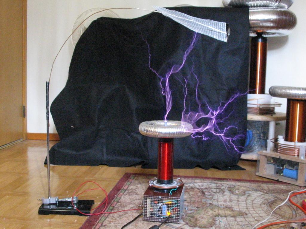
I replaced the primary with one made of 12awg on some 3.5" PVC instead of cardboard. A picture has been added above. I have now easily beaten my record. Max spark length is now 18" horizontally at only some 70uS ON time at 150bps. The new primary is much more efficient as well! Check out these numbers:
| Spark Length | Recorded Power |
| 10" | 33 watts |
| 14" | 88 watts |
| 15" | 110 watts |
| 16" | 135 watts |
| 18" | 180 watts |
Note that coil operation was at 120BPS or higher, otherwise I could do 12" at 1 watt at 1bps or something ;-).
I also note that all of the components seem to run cooler as well. This could be simply be that I'm not turning the pulse width up as high as before, but in any case, it now seems obvious that the method of using "lossy" components to limit current is not always the best way to go. I say go for the least loss, and simply reduce the ON time!
UPDATE: 12/13/04
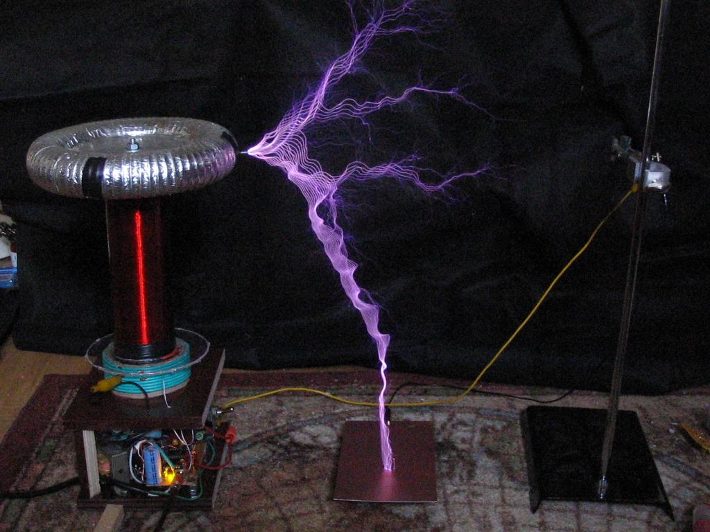
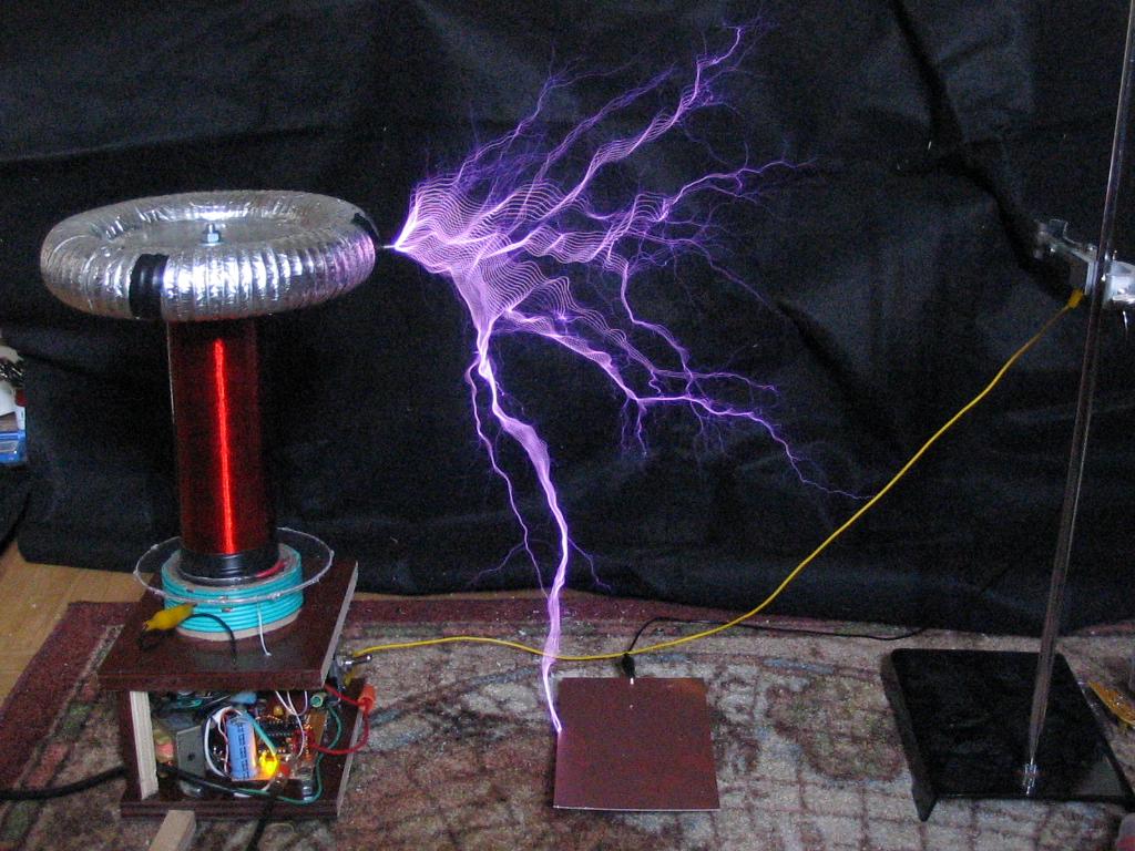
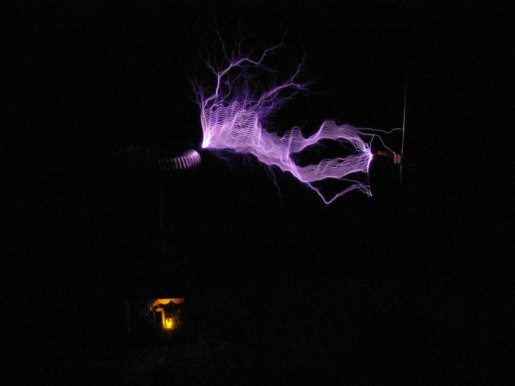
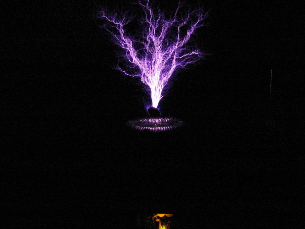
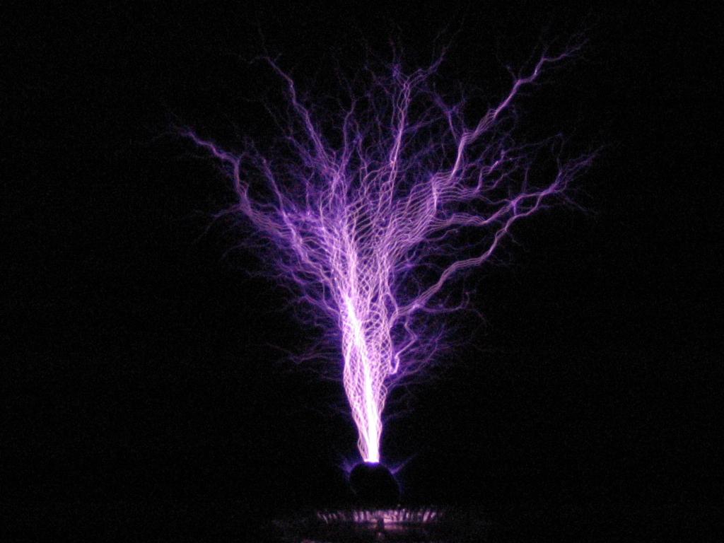
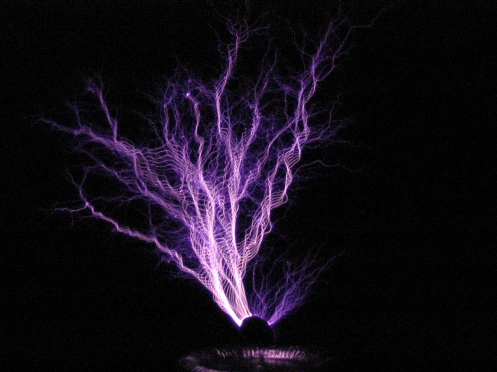
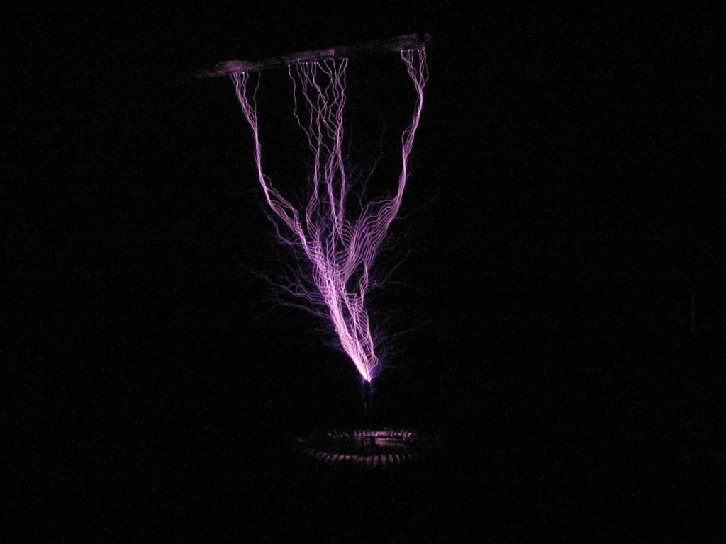
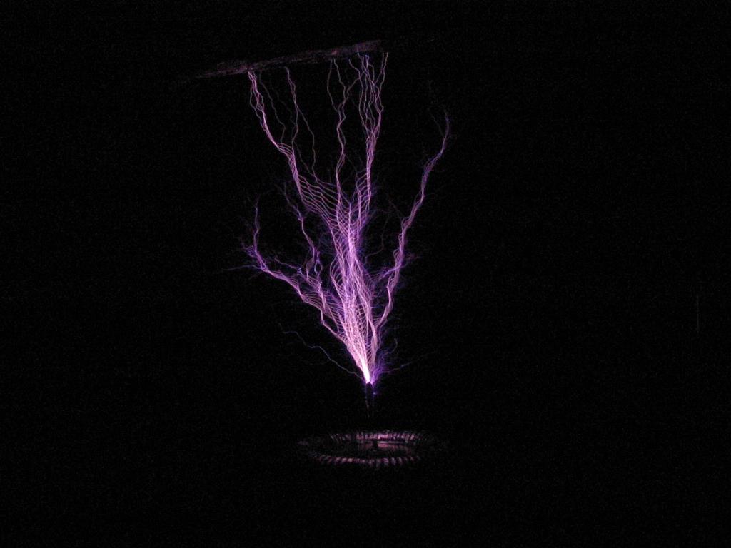
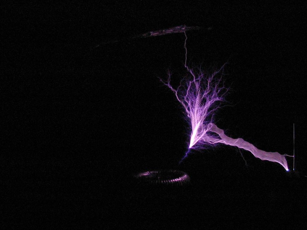
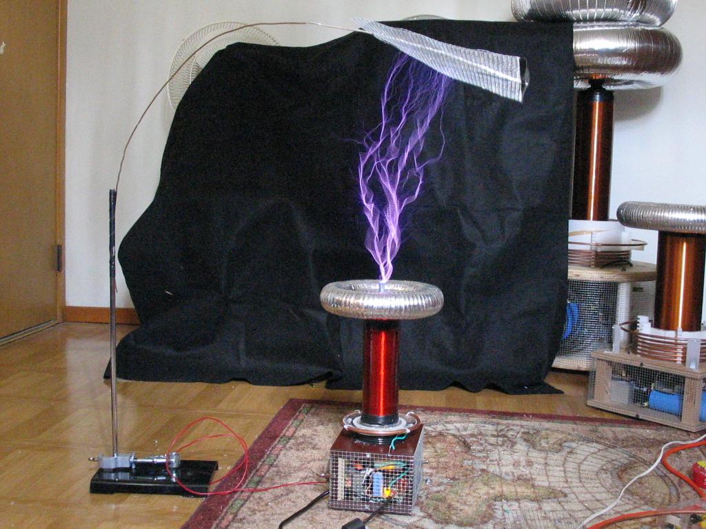
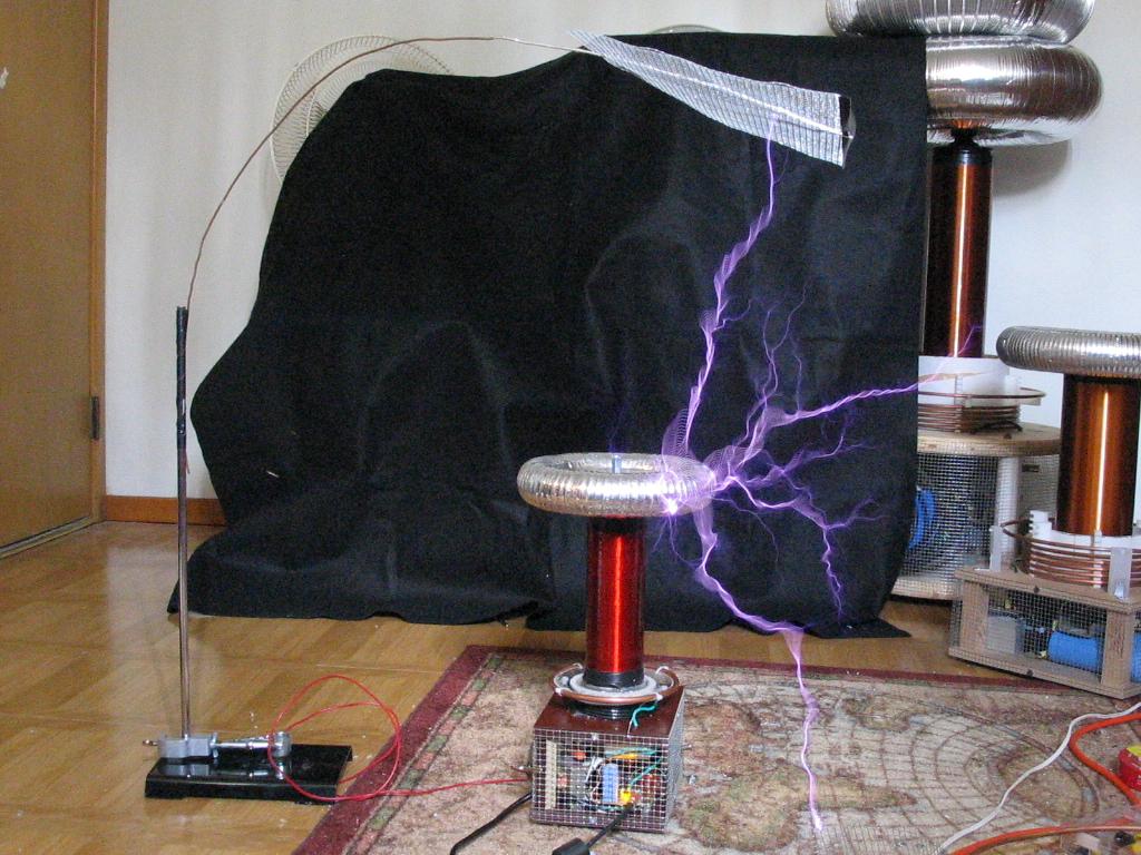
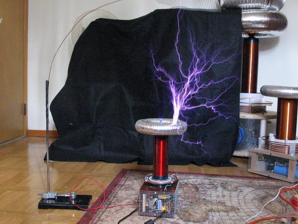
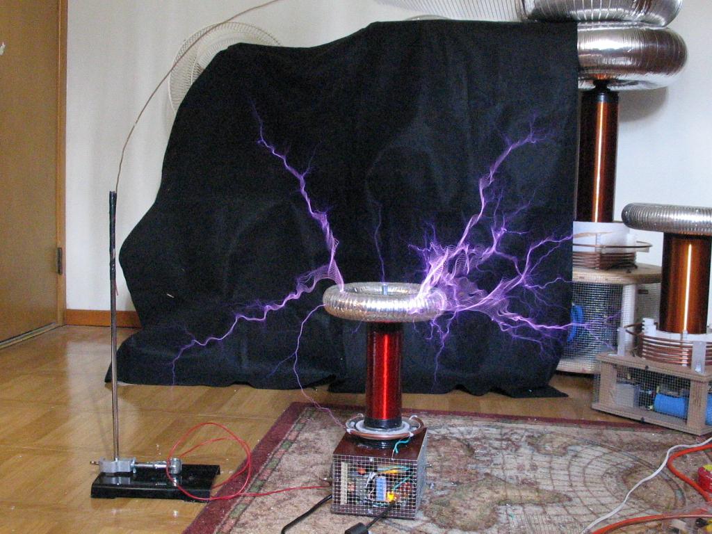
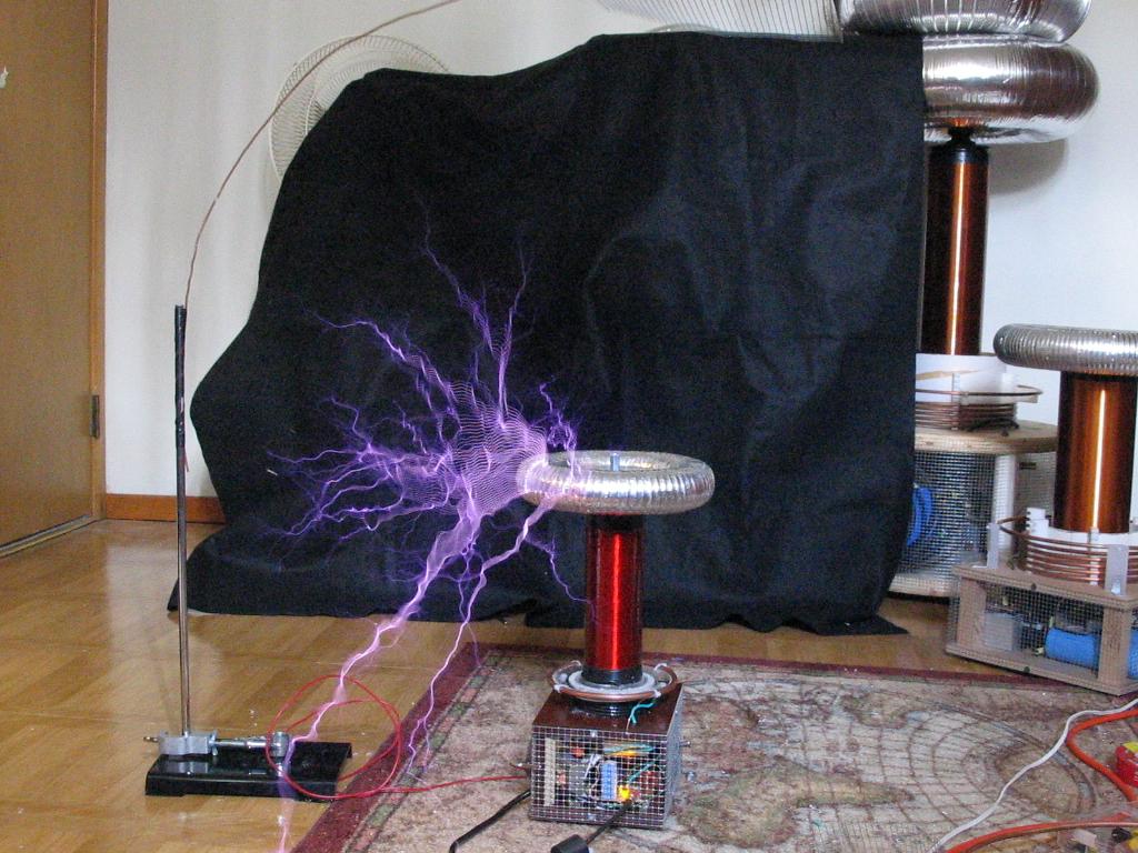
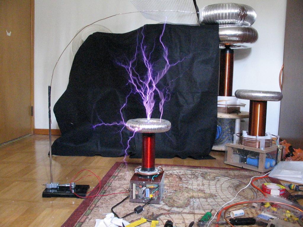
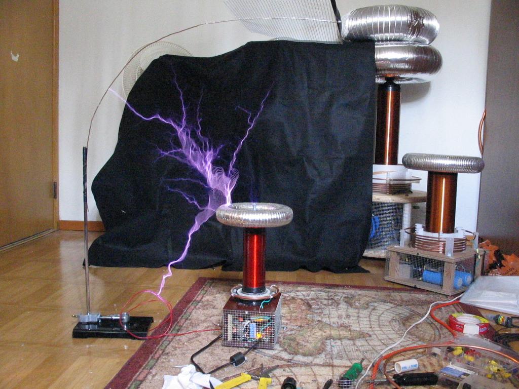
I added some metal screening around the base of the coil to prevent any failures due to sparks to the primary and electronics. So far it works great (as the pictures below will demonstrate). Spark length is up to 18" in some of the later pictures.
Here is a VIDEO of the coil in action (7MB .AVI)
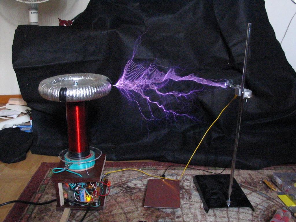
UPDATE: 11/23/2008
It just struck me how old this project is... last update was 4 years ago!
Well, it was time to make this coil more of a showpiece, and also test out my new driver at higher frequencies. This coil was still running on secondary base feedback too! So i built up a new driver for it and stuck it in a slightly bigger base. Also got a 8x2" spun aluminum toroid for it. It still has the same performance as before, though i found that with primary current feedback i was stressing the secondary coil more, and actually got some flashover. I have not determined why this is, possibly i am generating longer sparks and that is the cause for the higher stress, or maybe it is something fundamental to using primary feedback? Its an interesting topic. Im convinced that primary feedback is the only way to go with these things for high reliability, so im going to add more coatings to my secondary to make it more robust. It seems that tiny pin holes are responsible for the secondary tracking, so it may be possible to remedy this with better, thicker coatings of epoxy.