DRSSTC-2
Created 6/18/04
Updated 7/1/06
After pushing my original DRSSTC just about as far as it could go (racing secondary sparks set in when spark length was greater than 3X the secondary winding length: 60" spark to 18" winding). So several things brought about the DRSSTC-2. The largest sparks I have made to date were about 7 foot max with a whole bunch of 15kv NSTs. I wanted to use some of these larger IGBTs I had around. I was curious to see how the design could scale up. Finally, I wanted to teach those "spark gappers" a lesson in solid state engineering ;-). Also, I would be the first to make a SSTC break the 10 foot mark! Actually, to be honest, I hoped for 9 feet with the setup when perfected... but first light produced over 10 feet from a non-tweaked system!
This page contains pictures taken throughout the construction and revision process and may not reflect the final design. The schematic shown below is the latest version and has been developed from rigorous testing and has proven its reliability. From time to time this page will be edited with updated information (meaning some out of date information will be removed). I apologize for any confusion or inconvenience as a result of this, but I believe it will result in an easier to understand format.
Specs for my coil (as of 6/18/04):
| Secondary | 8" sonotube with a 45.3" winding of 26awg. I removed the outer layer of paper to remove the black writing. I then put 2 coats of poly, sanded, then wound. The coil was then coated with 5 more coats of poly. |
| Toroids | lower toroid is 26"x4.5" and the upper is 44"x9". This yields a secondary Fres of 45khz. |
| Primary | Conical with a 52 degree slope. 9.6 turns of 5/8" soft copper. Forms were made from some plastic cutting board. I.D. is 11" O.D. is 23.5". Coupling is about .18 with the secondary raised up 3.5" from the bottom turn. |
| Tank Cap | 15 strings of 4- .15uf 2kv CDE 942C caps. This yields .5625uf at 8kvDC. |
| Power Supply | Boost Converter |
| Other | Schematics below. |
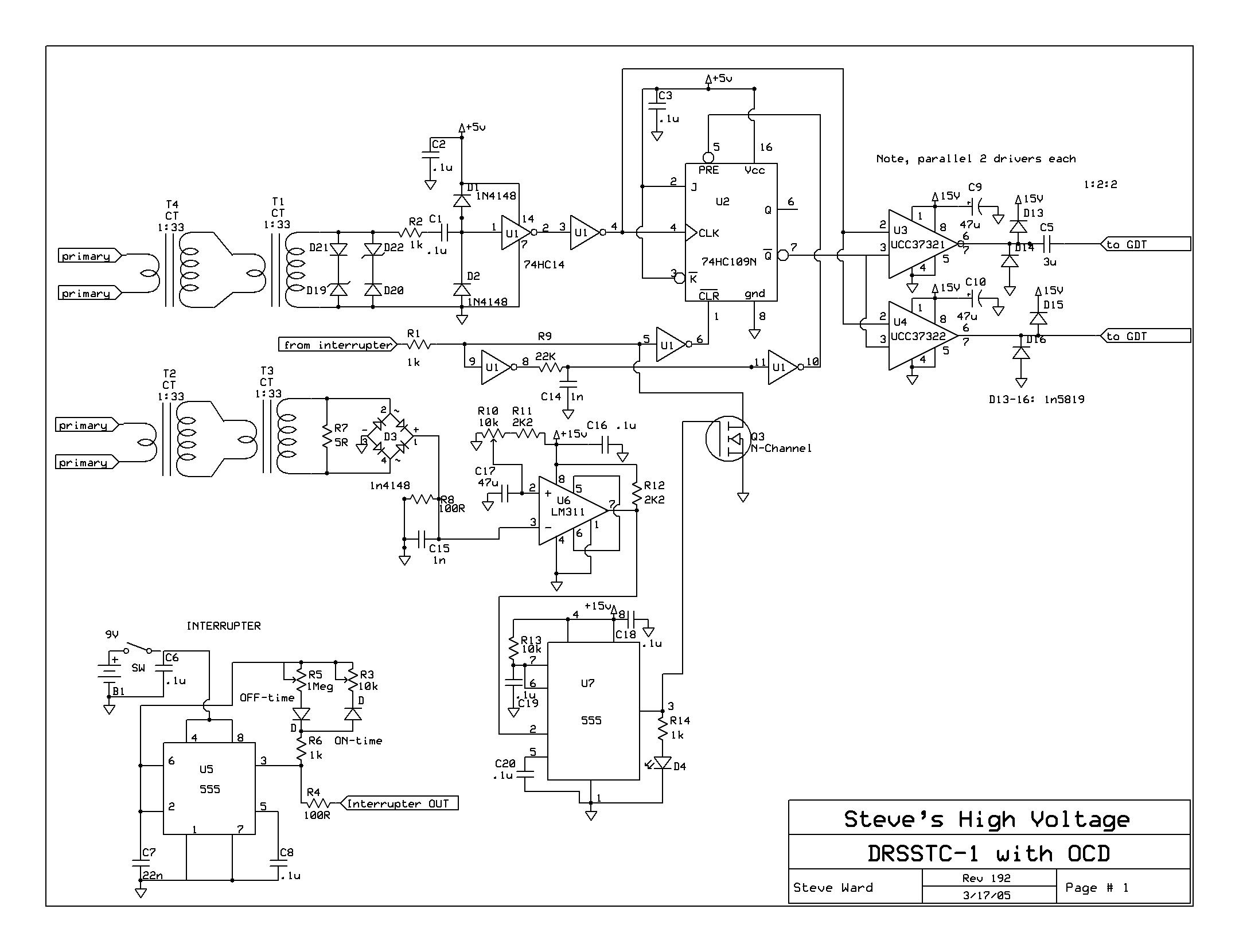
Controller Schematic (updated 7/1/06):
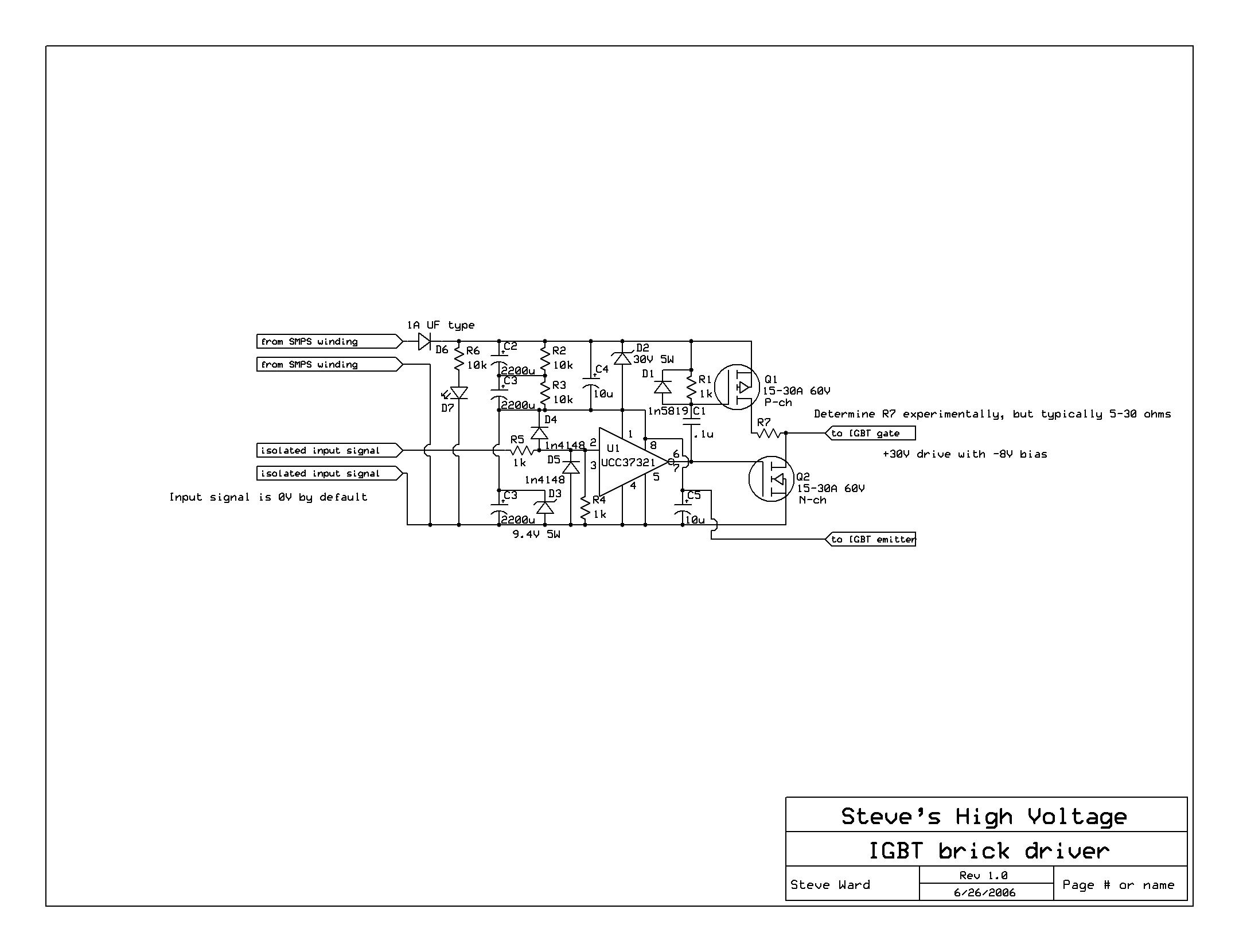
Gate Driver (updated 7/1/06):
Here are some construction pictures that may be interesting:
UPDATE (6/24/06):
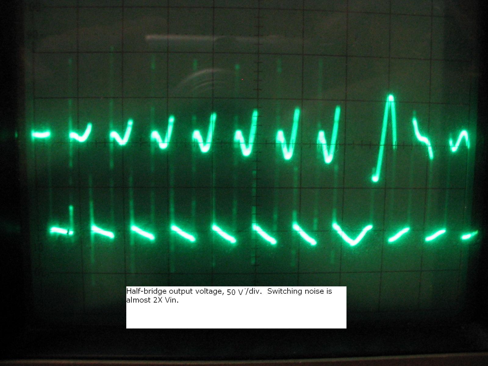
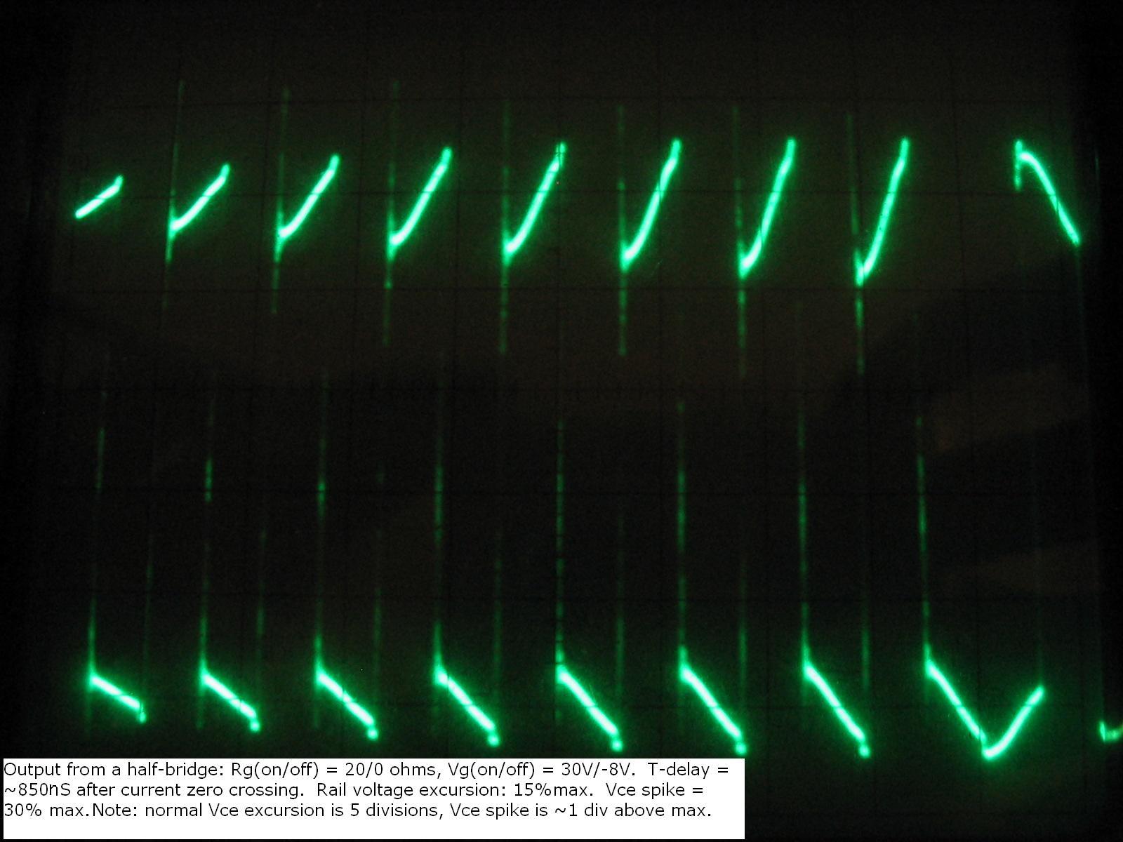
After powering this coil at 800VDC for extended periods of time, I experienced an IGBT failure (note that this was the first failure in over a year). The IGBT that failed also had its TVS string come disconnected (though the TVS's were not damaged). So I began to investigate what was going on here, and found a significant oversight in my original design. The problem, as expected, had to do with voltage transients. I turns out that the inductance between my large electrolytic capacitors, and the bridge, along with the decoupling film caps located on the bridge, had a resonant frequency of around 40khz! My rail voltage was ringing up to 160% of the input voltage, so at 800VDC input, this would have presented 1280V across the 1200V IGBT devices... yikes! Here is a picture of the output from one of the half-bridges in this condition:
The only way to fix this condition is to minimize the inductance between the IGBTs and the main filter capacitors. Simply putting small film caps on the IGBTs *does not cut it*! So I came up with this solution:
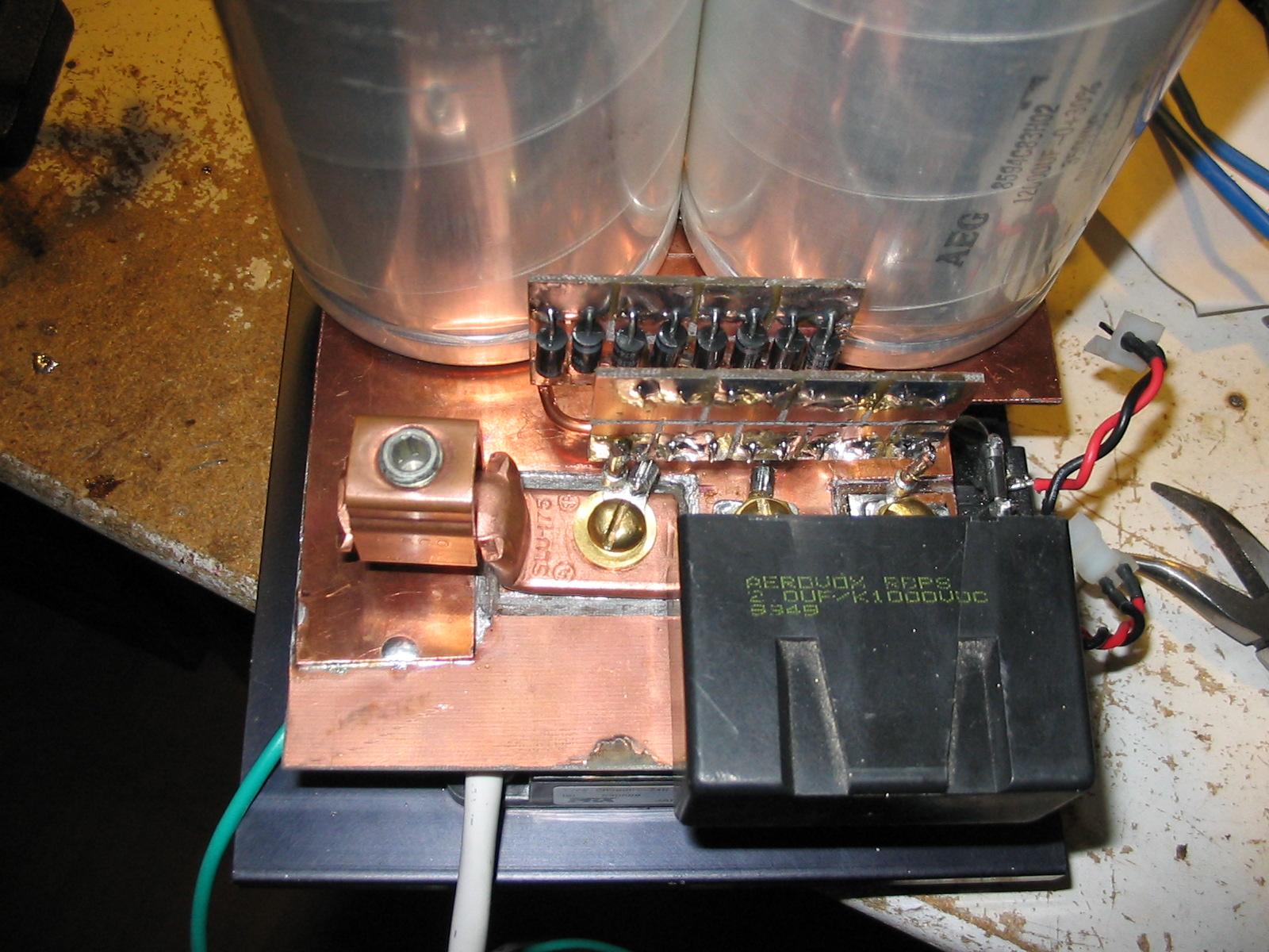
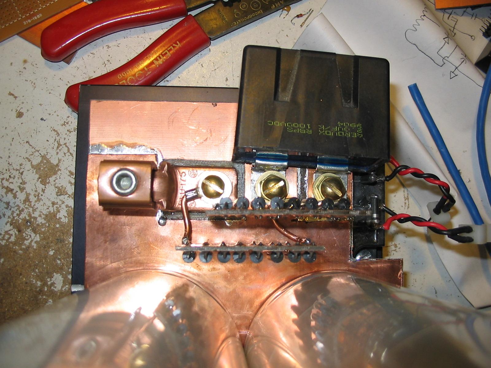
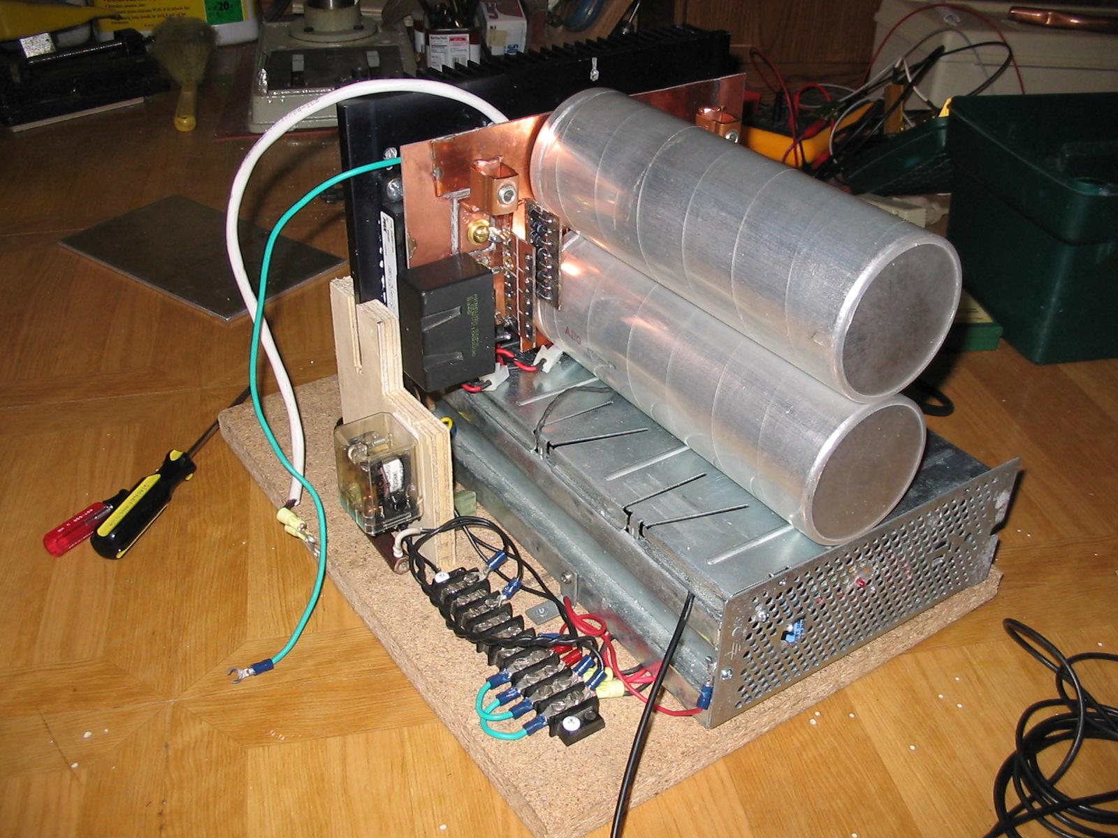
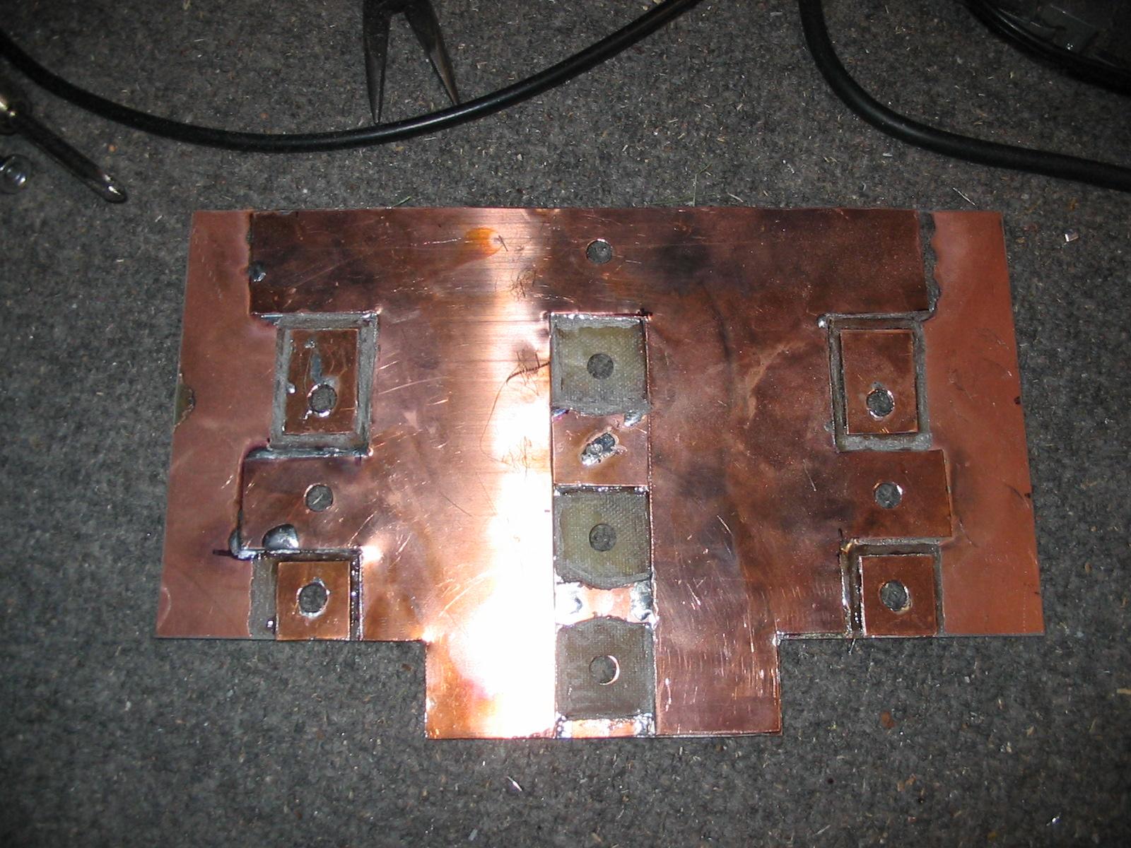
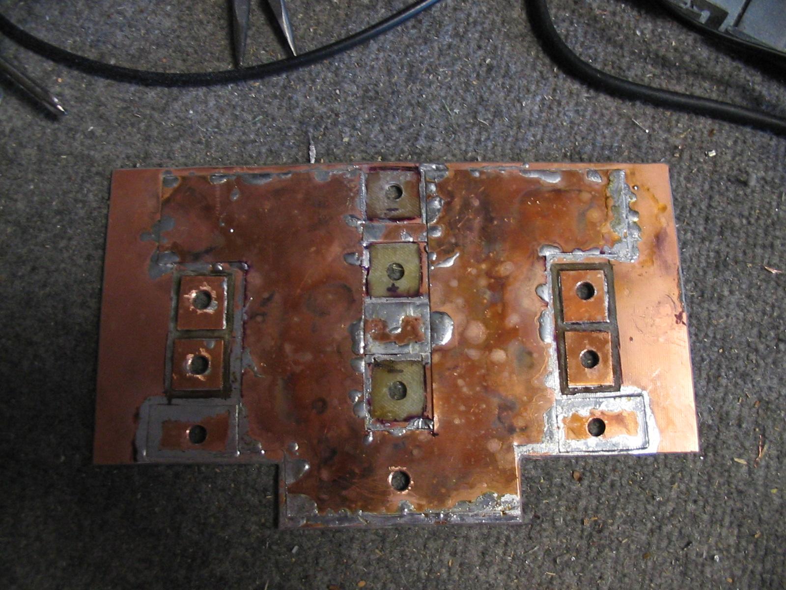
Basically, I started with some double sided 1/16" thick copper clad board. I drilled holes to mount the IGBTs and big DC capacitors. I then removed copper where I needed to break connections. The top of the copper clad board is the negative bus rail, while the bottom of the clad is the positive rail. The series connection of the 2 DC capacitors is done with a third layer that isn't shown, but its just between the 2 cap terminals. By having the supply rails in this "laminated" fashion, extremely low inductances are possible, because the coupling between the rails is very high. I bought some copper flashing from the local hardware store, and eventually learned how to properly solder it to the copper clad (you can tell which side I did first!). Soldering irons don't work here, so you have to use a torch, on its lowest setting, being careful not to singe the fiberglass PC board. The result is very robust, and the fiberglass board is strong enough to support the large electrolytic capacitors just fine. Also note that I've removed most of the film capacitors. They simply are not needed when the large electrolytic capacitors are so close. I kept the 2uF low inductance snubber caps for good measure, and because they fit the bridge so nicely.
So the results of this new bridge? Well, now the maximum voltage excursions are only 20% above the nominal DC input voltage (yay!). There are still some *extremely* fast voltage spikes present (talking 50nS long pulses), that are about 200% of the DC input voltage. There is really nothing I can do about this, because its caused by the inductance inside of the IGBT brick. I have mounted 800V TVS strings (8X 1.5KE100A) to help somewhat, but the IGBTs will simply have to absorb these very short spikes. I'm told that all IGBTs have some avalanching capabilities, but this does cause uneven heating of the die. My recent tests with the new bridge were great, though. The coil ran at 3500W, 700VDC, producing 9 foot streamers on a windy night! I'm confident it will hold up just fine at 7kW and 12 foot streamers when the time comes.
Update 7/1/06:
Had another failure despite the new low inductance layout. First, the conditions under which it failed. The coil ran wonderfully at 700V input at 100-120bps for a minute or 2, but right as I increased the break rate, failure followed within 10 seconds or so. There are 2 causes of failure that I strongly suspect, both of them are to be remedied. The first cause may be simple, the IGBT didn't have enough thermal grease and this might have cause it to overheat. The other cause (which I believe more likely) is that those short over-voltage transients that I mentioned in my last update are actually a problem and need to be taken care of. So, for the past week, I've been working several hours a day (both in the real world, and in pspice) to come up with a snubber design to take care of these spikes. What I found was that I had to sacrifice switching speed to reduce transients. I ended up using a 20 ohm gate resistor for the IGBT turn ON (I had to slow the turn ON because its the diode recovery that causes the spike). This along with a low inductance snubber produces voltage spikes of only 20% beyond the input voltage. It turns out that these IGBTs are not particularly low inductance design, so this was the real cause for most of the problems. I still need to test the new setup, but it looks promising from lower power bench testing at 200VDC input (500Apk primary current). Here is a scope shot of the Vce during the testing of the new snubber and gate drive setup:
I also found that my old driver had considerable delays, both in the controller and in the gate driver. The 15V controller logic was typically 5X slower than 5V logic, so I used one of my circuit boards I had made from another project. The gate drivers are new and use a P/Nch output pair with the Pch fet capacitively driven. This reduced the driver latency to about 1/4 of what it was with the old driver! I will change the construction pictures below to reflect the new changes.
UPDATE 7/2/06:
I tested the coil again tonight, and it seemed to mostly be a success. There were no IGBT failures, despite pushing the coil to the point of popping the 20A breaker several times. So something occurred to me tonight that I did not consider before. Both of my recent failures had something in common: I was running my 120V logic power from the 240 line that powered the inverter, so if the 240V breaker tripped, I lost 120V power. At first it doesn't sound like a real problem unless you consider what happens when all the control circuitry loses power. Well, the nature of my old gate driver was such that, if there was still signal coming from the control board, the drivers would continue to work, only that the lower "pull down" MOSFET would stop working if the negative supply voltage fell below -5V (the gate driver chip goes into UVLO). But, the "pull-up" MOSFET is still driven from a GDT, so it would simply turn the IGBT gate ON, but there would be nothing to pull it down! I tested this tonight, and this is in fact exactly what happens when my old gate driver lost power, the IGBT gate slowly falls from 30V to 5V or so, plenty of time for massive shoot-through. My big 6000uF energy storage bank on the H-bridge easily outlasts the tiny filter caps I used on my high-side gate drives, so its very likely that when the 120V section loses power, it can send all 4 IGBTs ON, causing it to short the filter caps and blow the IGBTs to smithereens. This might also account for the less than usual damage to the IGBTs upon failure. If the DC bus was already partially drained before the "event" then there would be less damage than if the IGBTs shorted out with full charge on the bus. So all this business about fixing those short voltage spikes on the bridge may have all been in vein, but they are improvements nevertheless. Hopefully the system is closer to being bullet-proof than it was even before.
I should note that the new gate drive may still have an issue with this
General Construction pictures:
Winding the secondary:
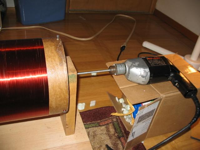
The secondary form is an 8" diameter concrete forming tube. I removed the outer layer of paper due to the black ink it contained. This ink showed to be slightly conductive to high voltages. It would likely cause internal tracking if not removed. I then alternated between coating the form with polyurethane varnish, and light sanding. After about 4 coats (with sanding between), the form was smooth enough to wind the 2300 turns of 26awg magnet wire on it. To wind the wire, I built a simple jig using a hand drill powered by my variac. The trigger is tapped down for max speed, so that the variac is in complete control. Its touchy, but you can achieve a relatively nice speed for winding. After the coil is wound, I coat it with about 8-10 coats of polyurethane varnish. Wooden end caps are screwed into the top and bottom, and bits of all-thread rod are used to bolt the secondary down to the base, and to bolt the toroids to the coil.
Building the primary coil:


The primary coil is made from a large HDPE cutting board that I cut up into triangles. I then used a 5/8" drill bit to drill circles that are tangent with the hypotenuse of the triangle. I then make a second pass with a dremel tool and cut-off wheel to remove the extra plastic, forming the holes into U-shaped cut outs for the copper pipe to snap into. The triangular supports are firmly mounted to the wooden base before I attempt any coil fitting! Working with 5/8" copper is real work, and takes a lot of strength to get it in shape. I later added a strike rail, which is not shown.
Printed circuit boards/electronics:
![]()
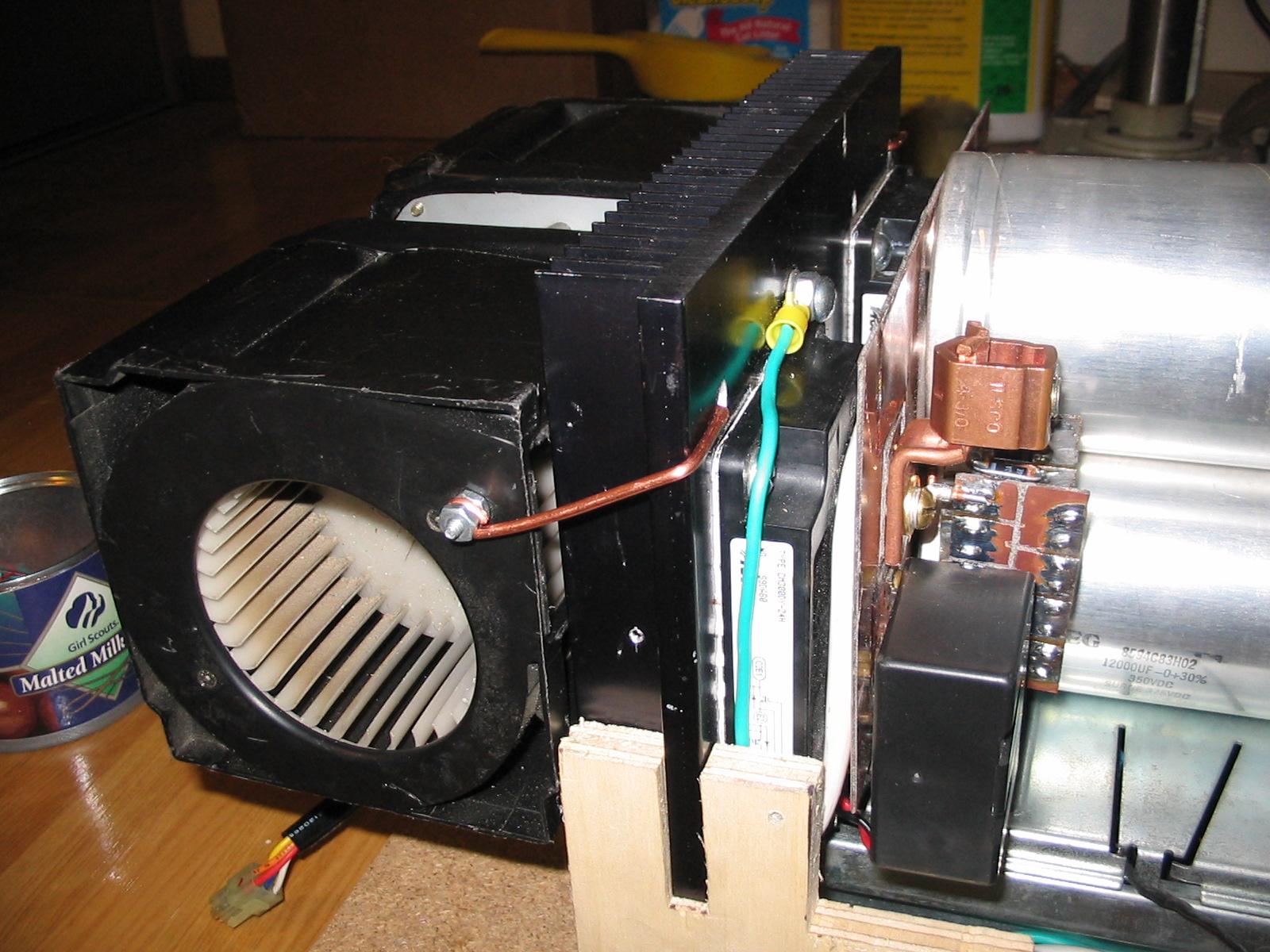
Here are various bits of the control unit. The first pic is of the 4 high-side gate drivers using surplus parts. Next is the SMPS I built to supply the control board and the 4 gate drivers. It was simply a TL494 controller driving a pair of MOSFETs. The FETs switched power from a 24VAC (rectified and filtered to 35VDC) transformer into a ferrite transformer with several output windings. The SMPS has no true regulation built in. I simply set the duty cycle of the TL494 for desired results and its worked well enough. Finally, the controller board, same design as the rest of my DRSSTCs. The gate driver output drives a GDT which provides isolated signals to each of the 4 gate drivers.
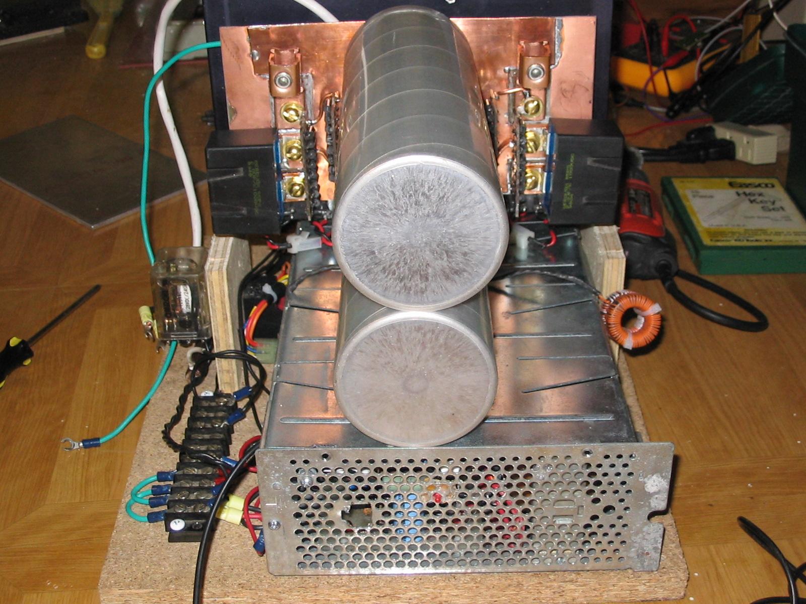
MMC:
15 strings of 4 series .15uF 2kV 942C series CDE caps. At .5625uF, it allows for lots of primary current :-).
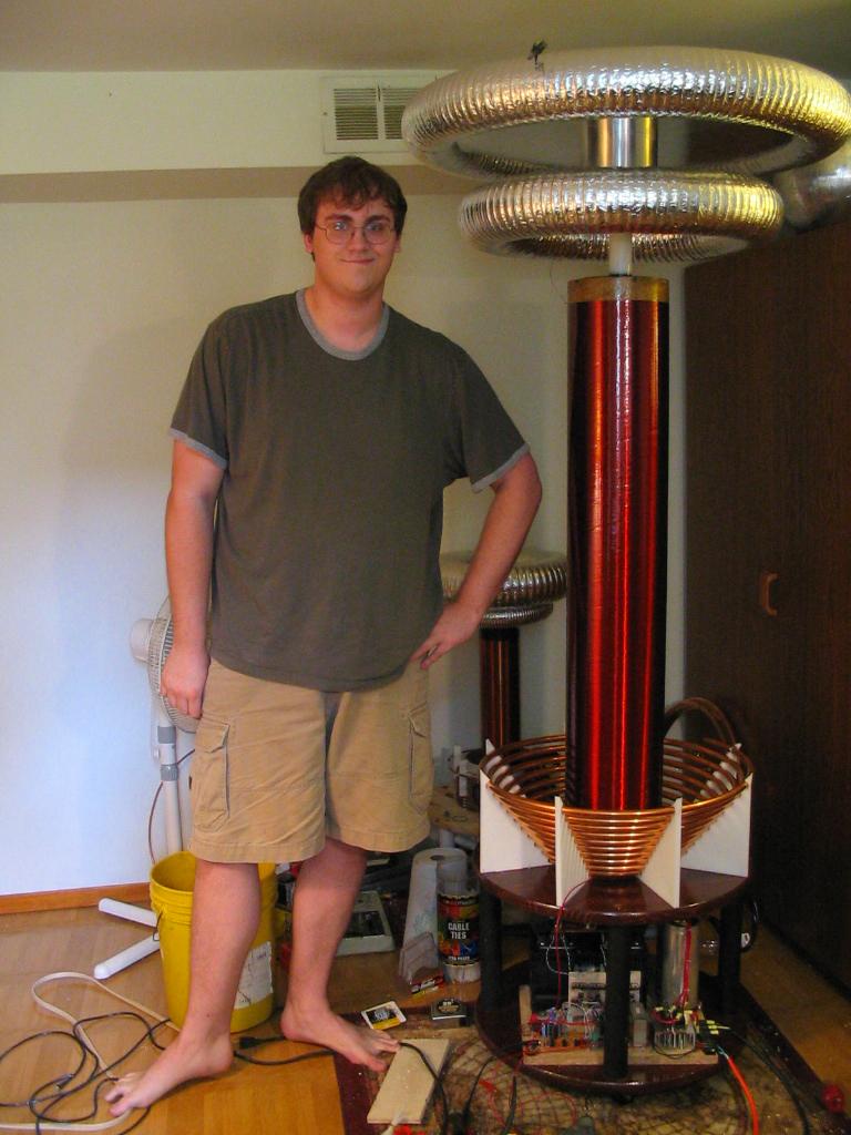
Finally, a picture of the creator next to the monster coil. For comparison, I'm 6'6" tall :-).
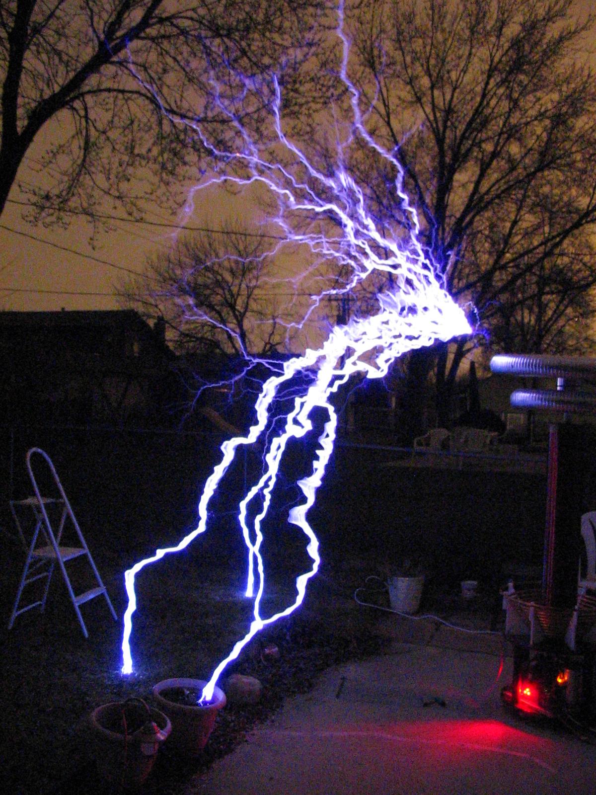
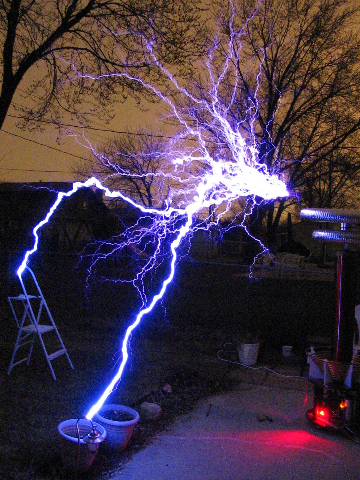
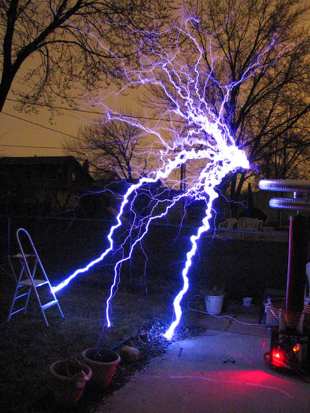
UPDATE: 3/18/05
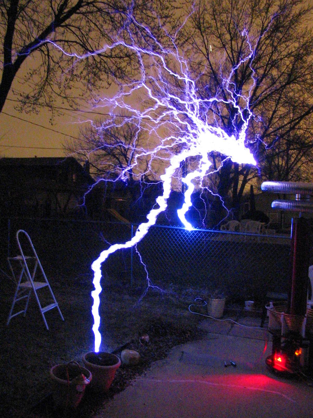
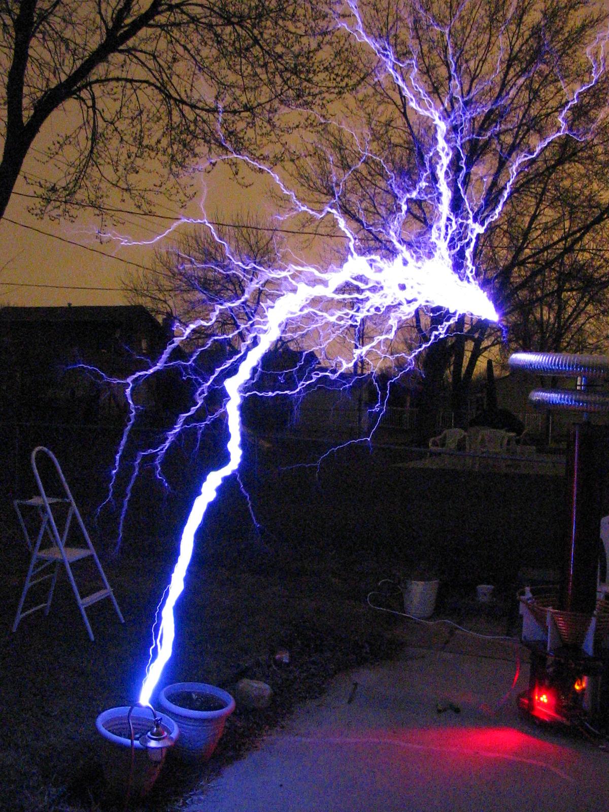
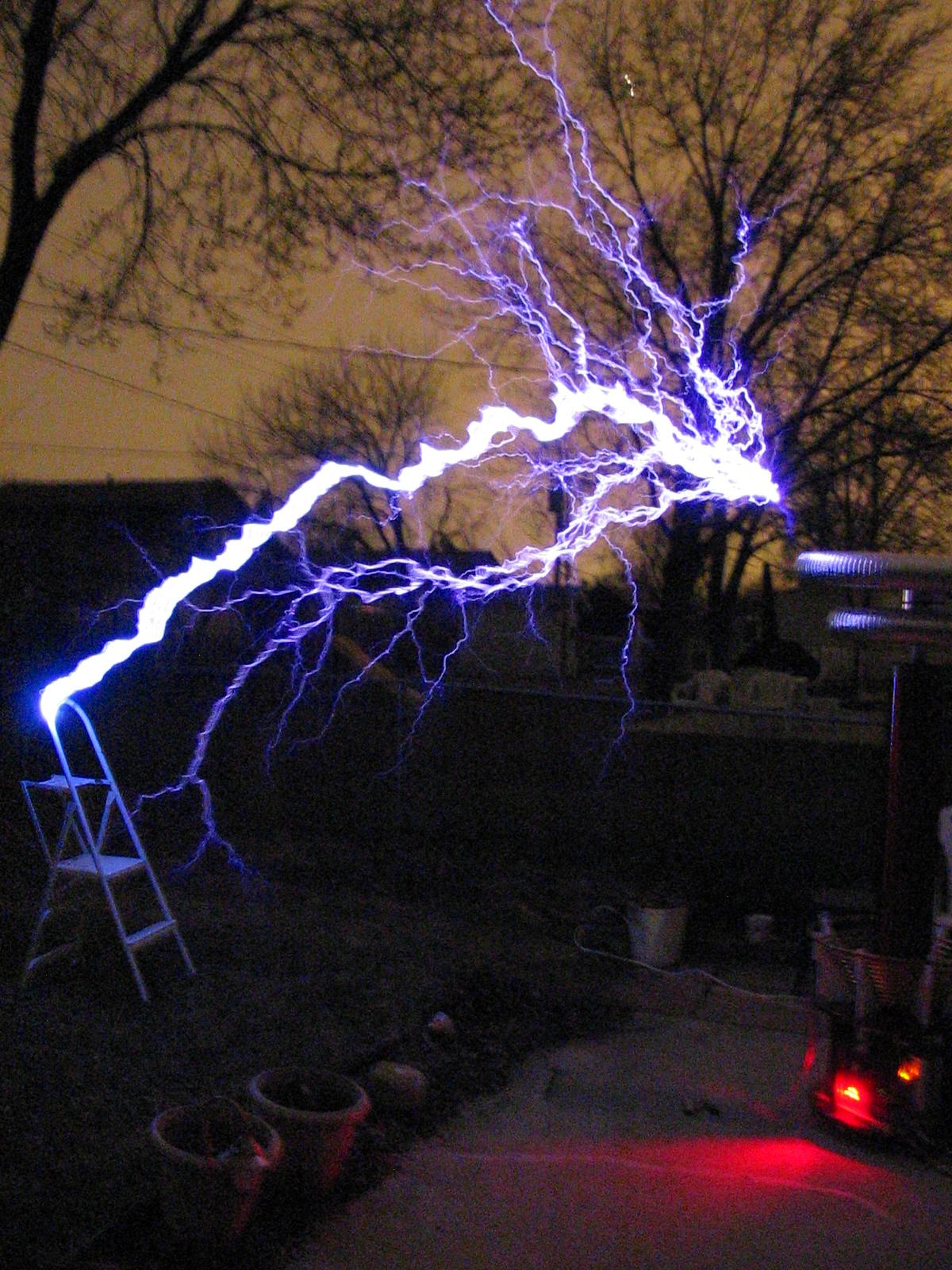
This coil is now operating on primary current feedback, and I must say the sparks are quite a bit more intense than before! I was only able to achieve about 10' on this run tonight. I only got up to about 200VAC input meaning about 560VDC on the H-bridge. Despite adding additional primary turns I was tapped all the way at the end of the primary again. I believe that is going to limit the performance for now until I can further modify the coil for additional turns. If you haven't, check out the new control schematic listed at the top of the page, its much simpler now and seems to work flawlessly. I'm using a remote interrupter now, just to make it easy to change BPS on ON time when I'm doing tests. Tonight I stuck to 300uS ON time and about 120bps. I don't know the power draw, but it didn't blow the 20A breaker or 20A fuses, so all is well! All of the components got just slightly warm out there in the cold (it was about 40F outside). Not enough heating to be of any concern, and I wasn't even using my cooling fans. Enjoy the pictures below, the arcs really are that bright!
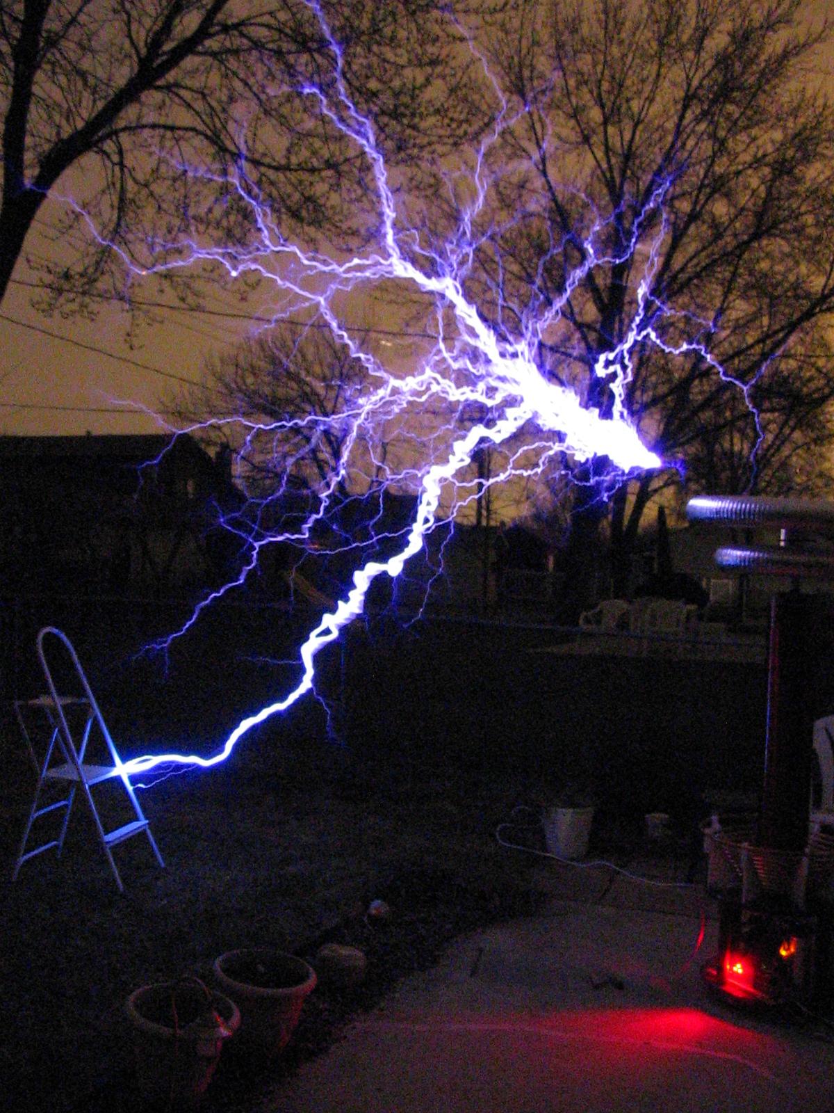
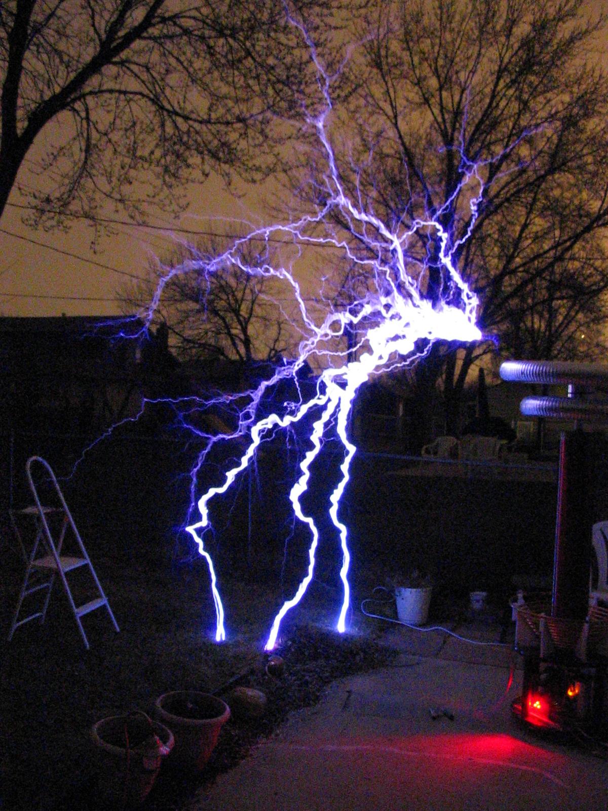
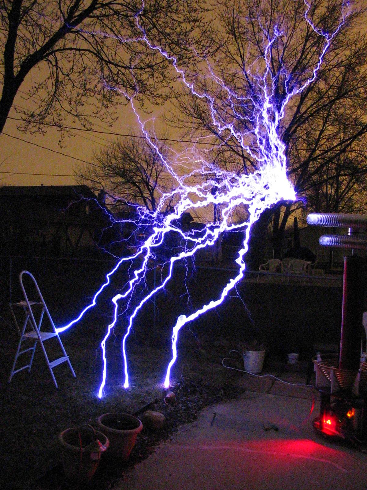
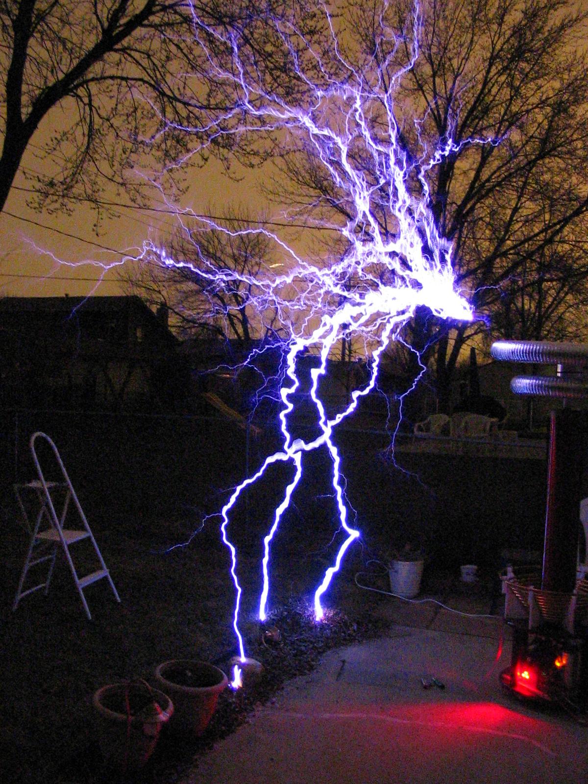
Christopher Hooper made an animated gif from some of the above pictures (thanks again Chris!):
