DRSSTC-4
7/12/08
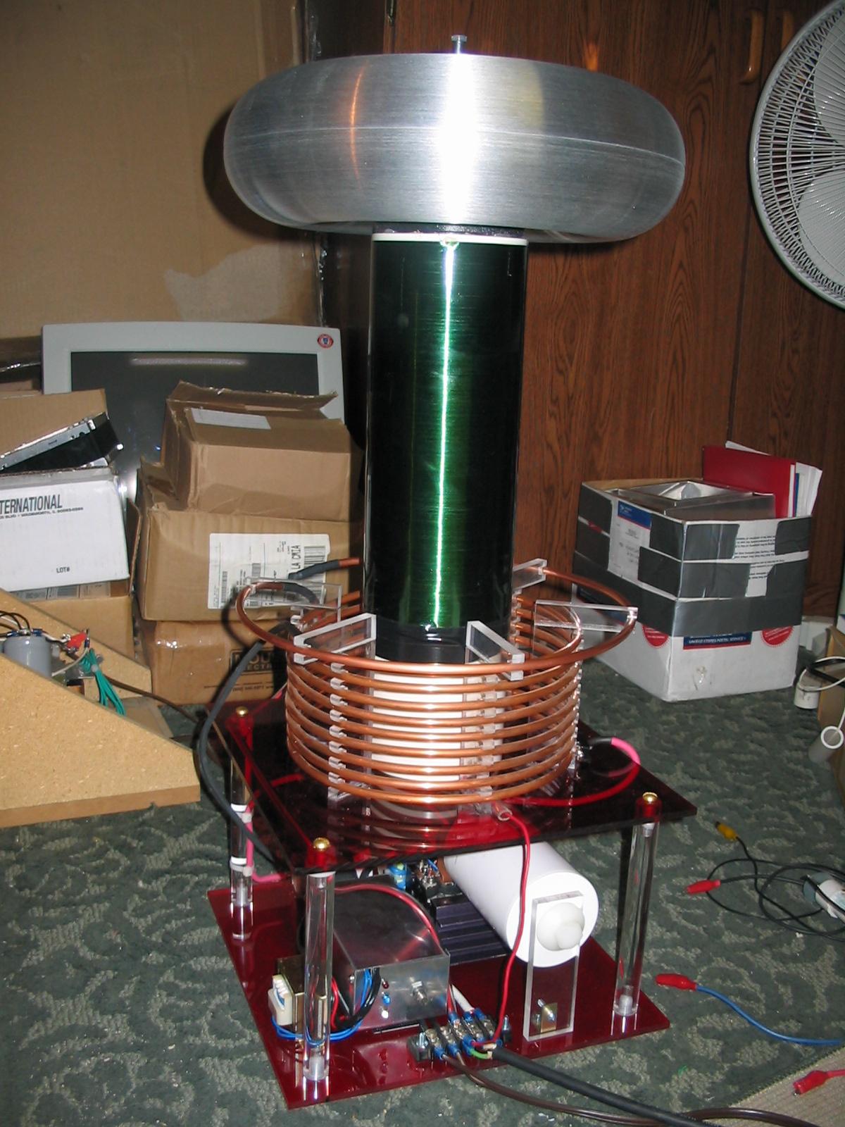
This project started as an attempt to make a "pretty" coil, partially inspired by Chris Hoopers work with plexi-glass. I don't have the nice tools or experience, so all of my edges go un-polished for now, but overall, its not bad!
The 4x13" spun toroid by John Freau is what really sets it off, his stuff is top notch for sure.
The coil is driven by a full-bridge of good old 40N60 minibrick IGBTs from Fairchild semiconductor. I only run this coil with 120VAC input, and no voltage doubler, so 160VDC provides plenty of voltage headroom for now. The current limiter is set at a modest 350A.
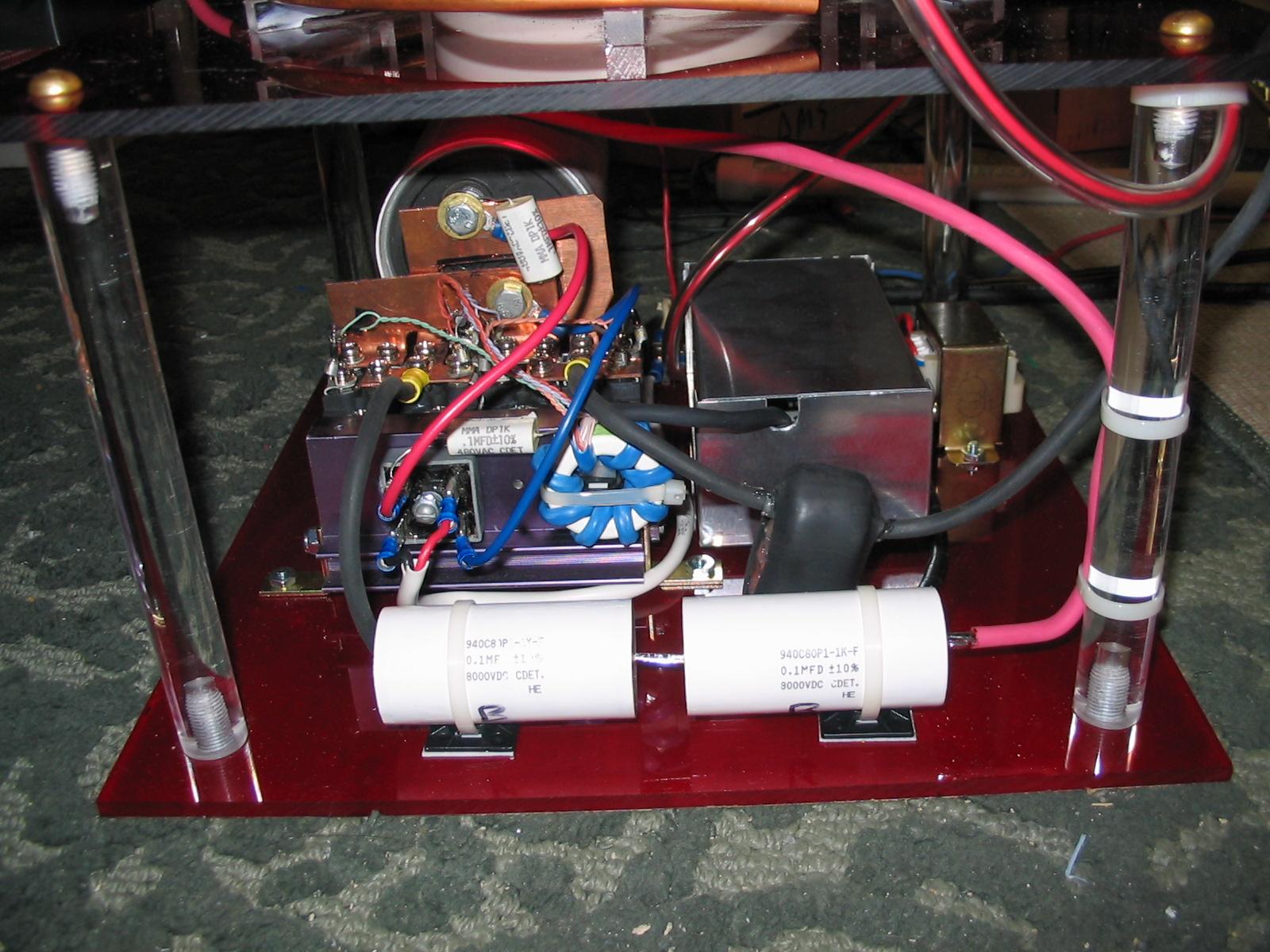
Notice a few things here. The H-bridge is constructed in a compact, low inductance layout, in fact you simply cant get the IGBTs any closer together, they are just about touching. The bus cap is a 3300uF 400VDC cap made by Rifa, its got the nice big aluminum studs on it, hopefully meaning that its built for abuse... seems to work either way.
The GDT uses my old trick of winding an entire section of cat-5e network cable around the ferrite toroid. I had a nice 1.5" OD toroid so i could fit plenty of wire on there. Each "striped" conductor is a primary wire, and the colored conductors make the 4 secondaries. Parallel up all the striped conductors on the primary side and you get a pretty good coupling between everything. Because my driver is running at 24V with a full-bridge drive to the GDT, i no longer have to use a 1:2 winding, its simply 1:1 now for 24V gate drive. I use a 5.1ohm resistor and 1n5819 schottkey diode on each gate drive lead so as to slow down the turn ON transition, and add a bit of deadtime. The gates are protected with 6KE30CA TVS diodes.
Also featured in the picture is my MMC, but you can hardly call it that with just 2 capacitors. The caps were special from CDE, rated 8kV at 100nF each. The 8kV is a DC rating, and in testing i found the caps snap over at a reasonable rate with about 3500Vpk applied. After about 4kV, the rate at which the dielectric punches through is quite excessive! I ran these caps for about 50 hours at 3500Vpk, losing only 1% or less of rated capacitance, so that seems acceptable for hobby use. My current limiter is thus set to kick in just below 7kVpk on the primary side, so the caps should stay healthy for some time.
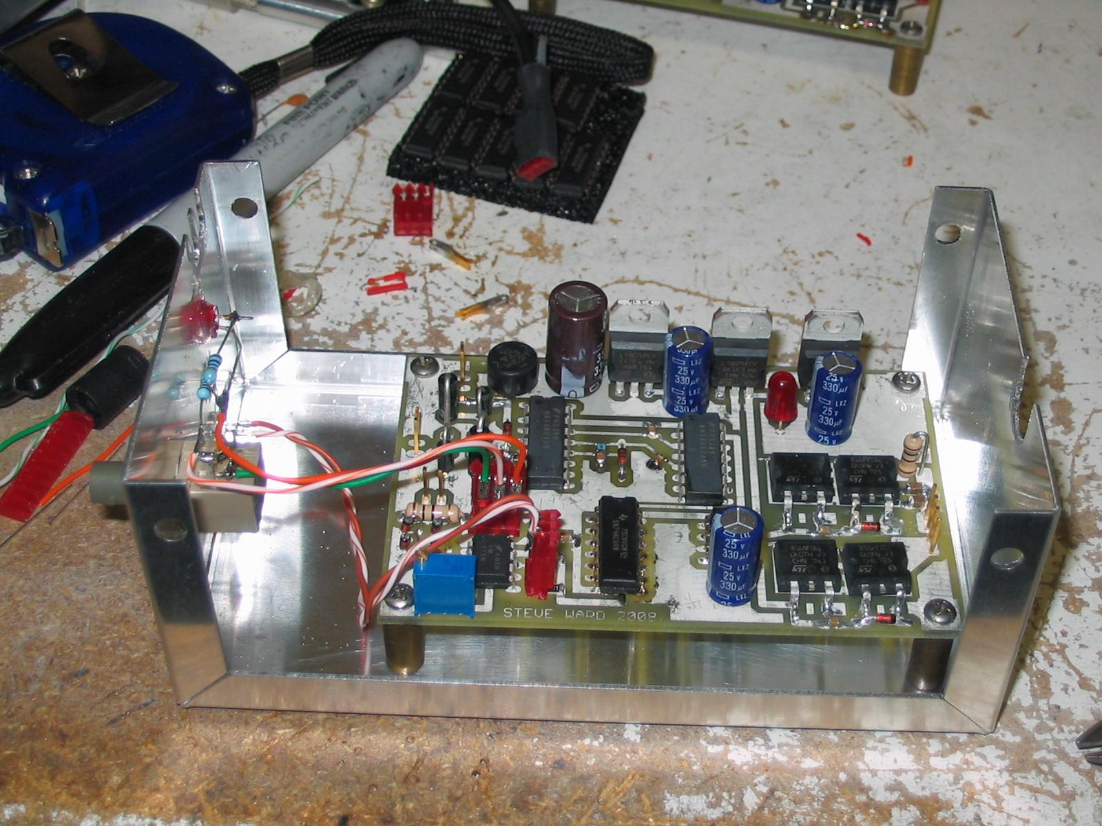
Seen here is my latest driver setup. Some more details can be found here. The 3 LEDs are power, signal indicator (from controller) and over-current limit. The aluminum box mainly serves to provide shielding for the fiber optic receiver, and serves to nicely package the driver all in one box. If not properly shielded, i have had these Rx's extend my pulse widths excessively (sometimes making a big fat yellow spark). Its noise induced from the secondary coil, as the problem does not exist when driving the primary system alone.
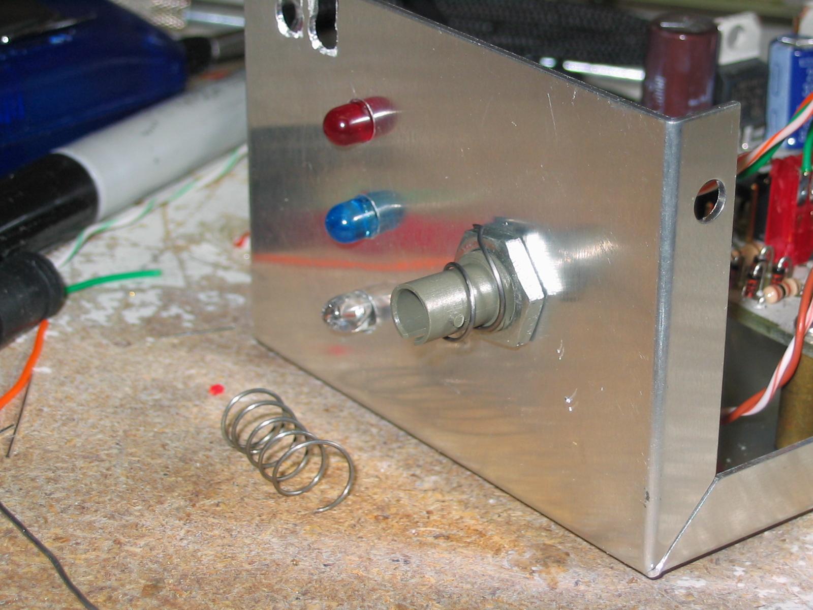
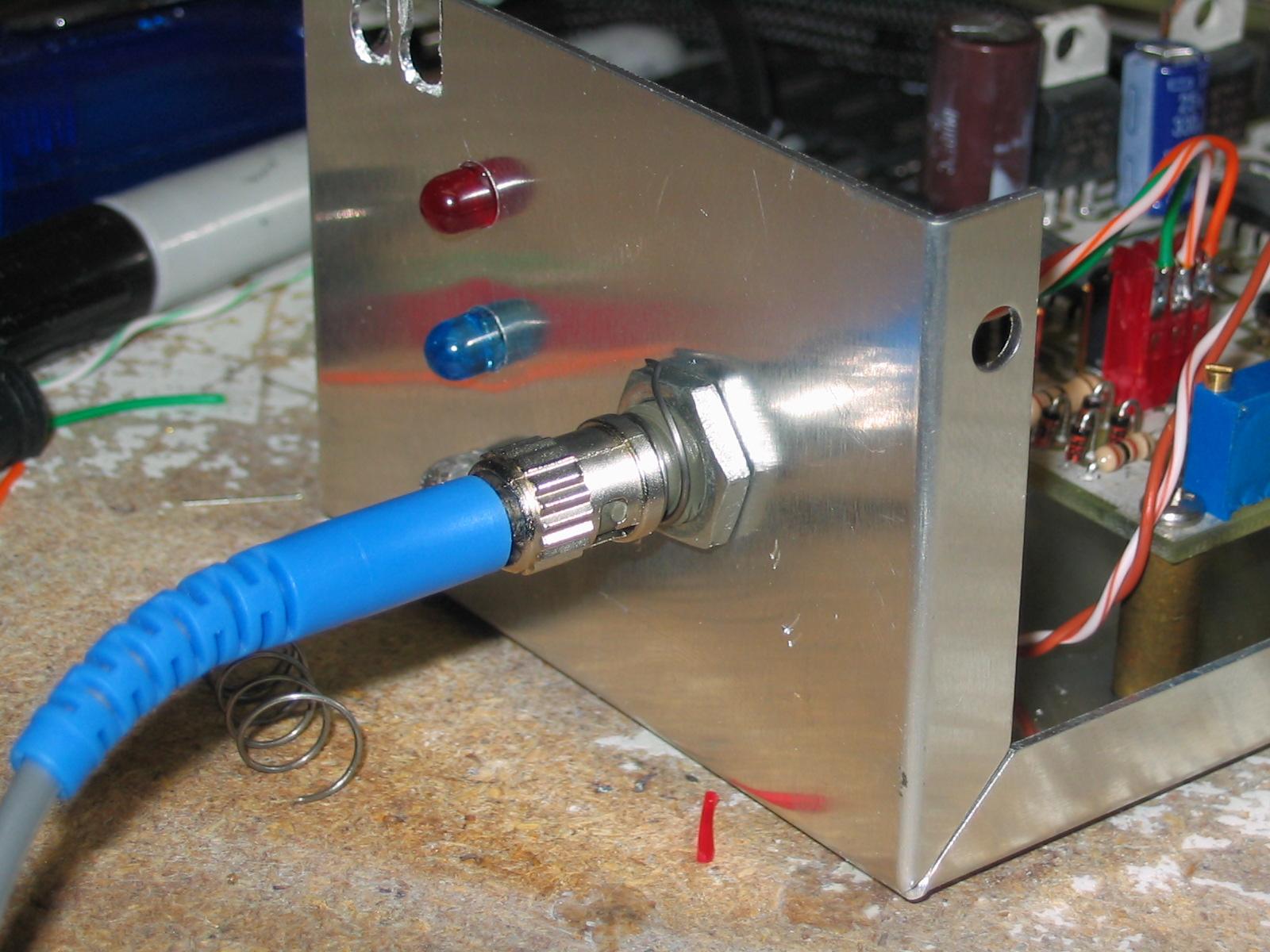
But the metal box itself wasn't enough! On a whim, i tried grounding the metal collar on the ST fiber cable, and bingo! that was it! I later read in an application note about these receivers that they are extra sensitive to electric fields, and its recommended you buy the full metal encased ones for noisy environments. Well i cant find the metal ones so sticking a steel spring between the box and the metal coupling seems to achieve the same effect, good enough for me.
One problem that has bothered me for some time is that these fussy solid state electronics seem to explode under some nasty conditions, one of them is having the secondary arc back onto the primary circuit. This produces a wicked common-mode voltage, which must find its way back to the secondary base someway or another, usually resulting in blown up IGBTs and other stuff. This seems unacceptable to me! By the use of proper shielding and grounding techniques, I knew the problem could be resolved and so I gave it a go with this setup.
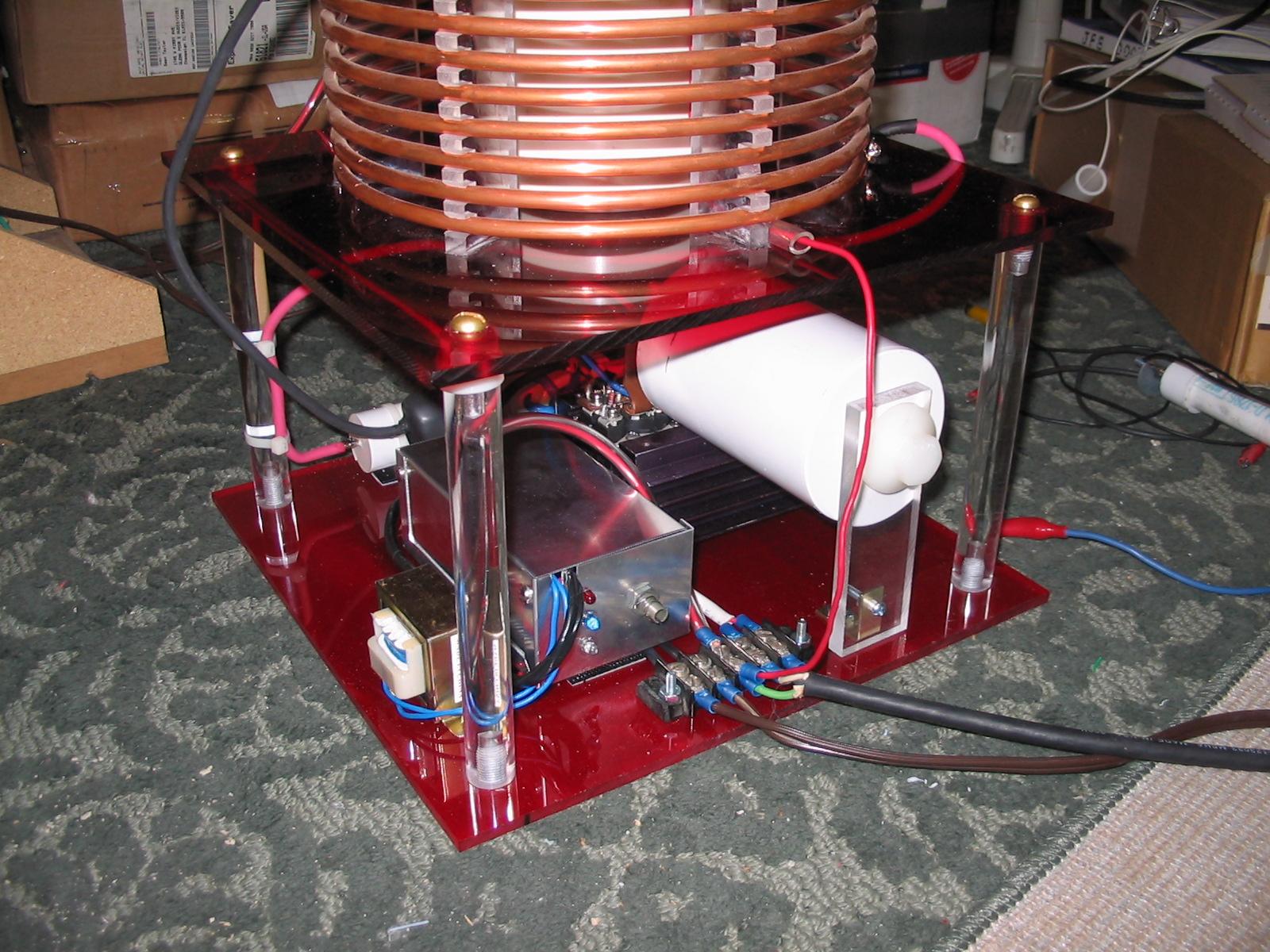
I awoke this morning to find that my strike ring had been sabotaged:
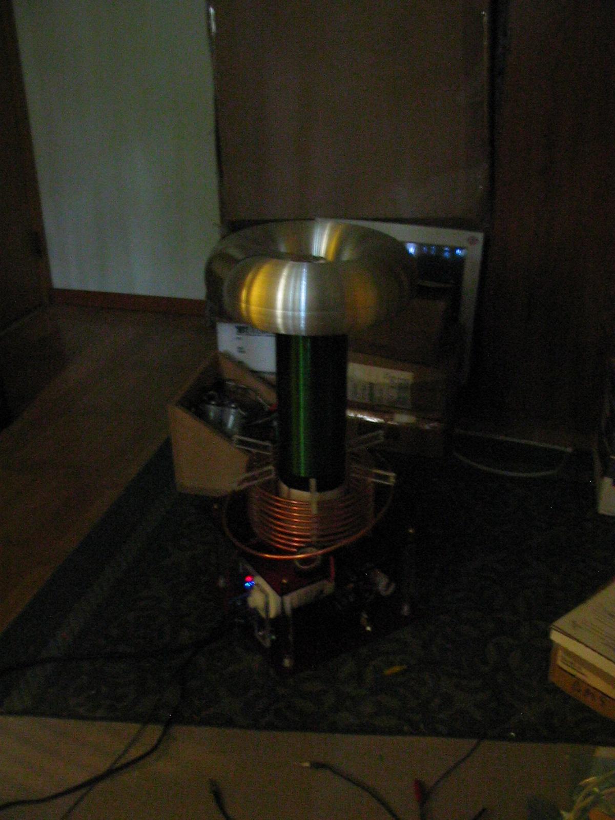
Its hard to tell, because apparently I didn't think to use a flash or turn the lights on, but you can still see the strike rail just laying there, well below the primary coil!
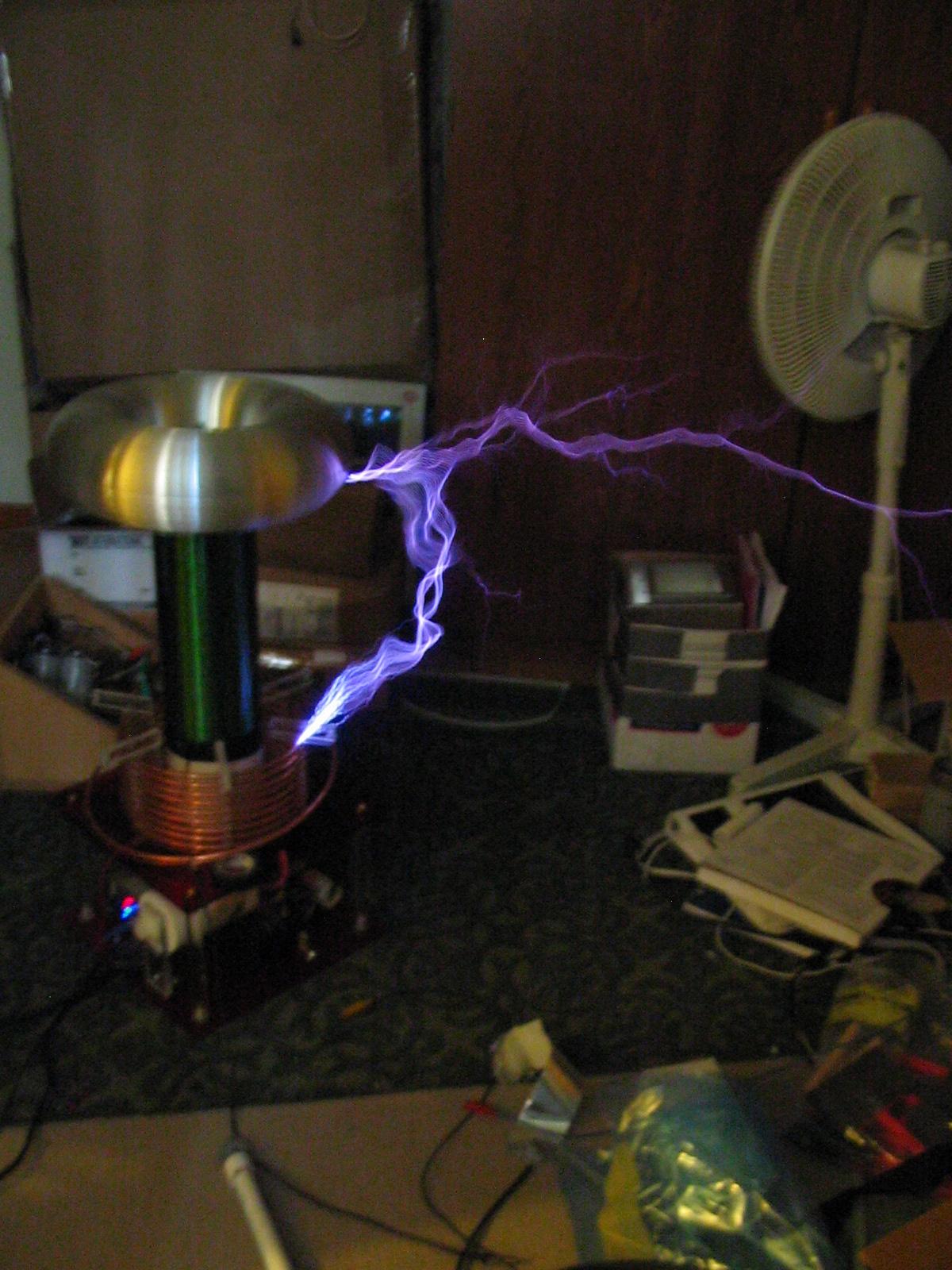
Well, time to see what my grounding scheme has done for me, lets be foolish and put the breakout point right on the side of the toroid:
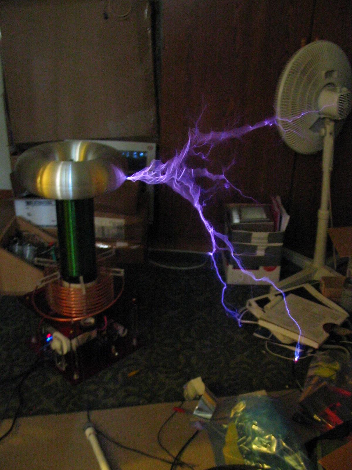
Oh man! those sparks are getting close! Until finally...
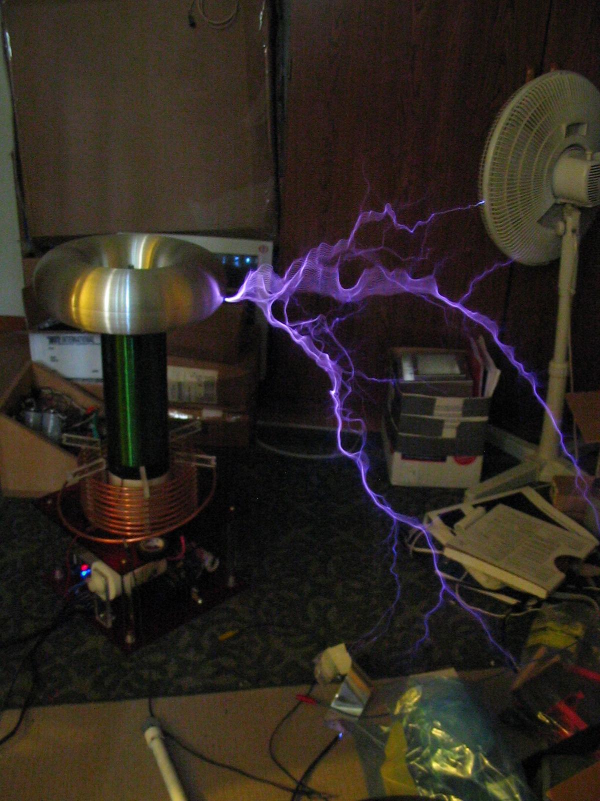
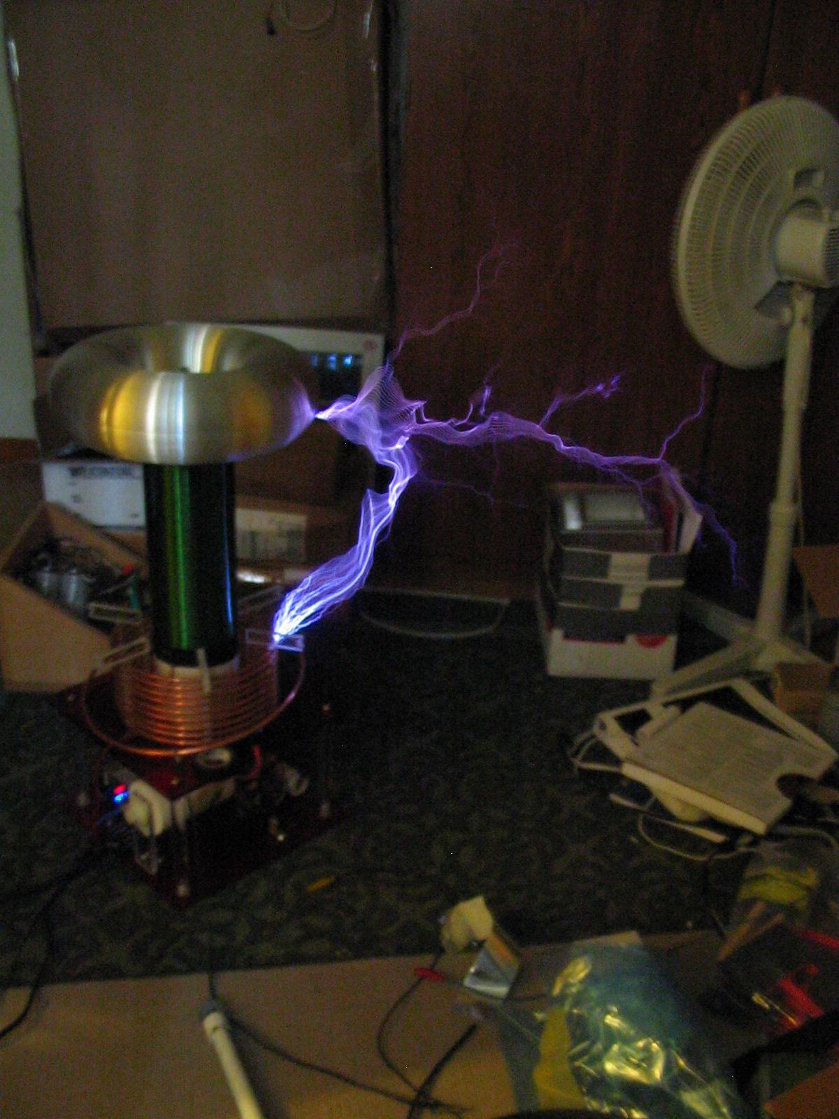
Ooooh, good one. Hey, look at that, nothing blew up.
So for those who want to know, here is how I wired this system. Notice that if the coil arcs to the primary system, either the IGBTs or diodes (which are always there) will let the current go safely back into the DC bus caps, where it can couple through C3 (a 100nF PP film cap) to the ground connection of the secondary coil. If the capacitor was not there, then it would likely blast through to the heatsink and destroy the IGBTs insulation. Or, it will find some other way. The idea here is simply to provide an excellent path for the streamer current to take, simple.
But this brings up another issue. There is common mode switching noise from the H-bridge that gets coupled through the GDT to the low voltage electronics. This shows up as nasty spiky ringing junk on your low voltage board. Connecting the low voltage PCB ground rail to the ground set up for the H-bridge allows the common mode currents to get even worse than if the PCB was left floating (because then it can only present some stray C to the drive, or couple through the power lines supplying both systems). So it seems wise to ground them together, but what about this switching noise junk? Well, there are a few solutions, wind your GDTs with an extra faraday shield between the primary and the secondaries, and let the extra shield keep all the junk on the bridge side. I tried this, didn't see a really solid improvement, so I tried simply adding common mode inductance to the GDT primary, via ferrite beads. This seems to work great because the extra inductance limits the current that gets coupled through the loop. I'm told this can increase the total gate drive inductance a bit, but it doesn't seem to adversely effect my system. The noise reduction on the PCB is quite apparent, so its doing something.
There is one final issue to address here. This idea works OK for smaller systems for sure, because its been shown that using AC mains ground is "good enough" for these smaller coils where ground currents aren't as huge. On a BIG tesla coil, its strongly advised to be using a separate ground rod for the tesla secondary and strike rails. But, now if the coil was to arc to the electronics, it would have to find its way back through the house wiring to ground, or some other, possibly worse, path. So it seems that for this scheme to work, you would have to connect RF ground to mains ground. My initial thought on this is that its probably just fine, because the ground rod should provide proper grounding for all the RF currents. It should appear to be lower impedance than the AC line ground hopefully keeping all that junk out of your house wiring, and at the same time keeping your system safe from primary hits. Please keep in mind, this is unverified!